285 Issue 1 - Service Manual - Iceberg
13
5.5 Water Supply to the Evaporator Module
The Evaporator Module’s water system is designed to operate with a water supply pressure
between 300 kPa and 1000 kPa. If the supply pressure is excessive, a field-supplied pressure-
reducing regulator will be required. If the pressure is insufficient the Cooler’s operation will be
compromised. In areas subject to water pipes freezing the primary drain should be insulated to
prevent damage to the cooler.
•
Ensure the supply piping has been flushed before connecting it to the Cooler.
•
A registered licensed plumber must install the water supply piping and connection to the
Cooler in accordance with the local water supply regulations.
•
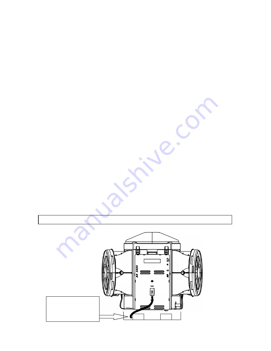
An isolating valve on the supply pipe must be placed and secured in the Safety Tray
beside the Evaporator Module so that it does not dislodge. This must be provided to
facilitate isolation of the water or to disconnect the water supply piping when servicing.
•
Non-return isolating valves on the water supply are not recommended as they may cause
damage or lock up the Cooler’s inlet mechanism where high lock-up pressures or freezing
water in pipes may occur.
•
For the owner’s convenience, an additional isolating valve may be provided at ground
level to isolate the water supply.
•
The water supply pipe must be supported and secured so as not to place strain on the
Cooler’s water connection fittings or cause water hammer noise.
•
Water quality should be checked and filtration fitted where necessary e.g. tank or bore
water.
•
The connection size to the Evaporator Module is 1/2” BSPF.
•
Flow stop valve is fitted on the water line.
6.0 Inlet Connection
The water inlet connection point is on the “
Evaporator Module
” within the roof space. The
connection size is 3/4” BSPF and is located on the Aquastop, a device secured to the end of the
braided hose. A bi-directional water isolation valve is required at the unit for servicing and it
shall be connected directly to the Aquastop. After connection the ball valve shall be secured
inside the safety tray, a position and cable tie has been made available for this, refer to Diagram
Aquastop at the
Water tap end of the
braided line is ¾”
BSPF.
Note:
The 3/4” BSPM thread on unit is plastic, be careful not to cross thread.


