8-Button Wall Plate Ethernet Keypad User Manual (LB-KP8E-ICP / LB-KP16E-ICP)
21
CONFIGURATION
THE BACKGROUND
LIGHT BAR ALLOWS
USER TO INSTANT-
LY CHANGE THE
LEDS LIGHTING
PERCENTAGE
BASED ON THE
ORIGNIAL ILLUMI-
CONNECTIONS
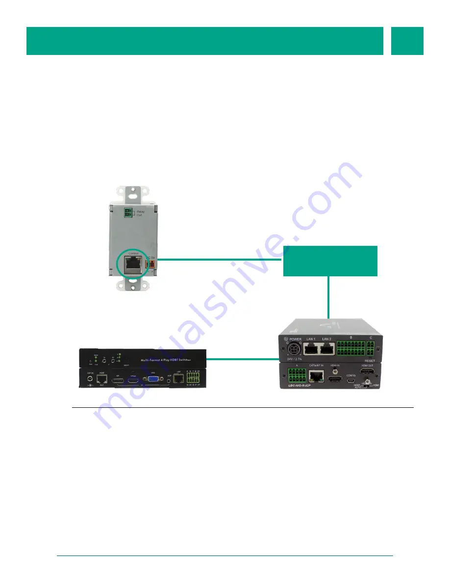
The LB-KP8E-ICP must be connected to the same network as the LBC-H/O-R-ICP per
Figure A
Ethernet Switch
Figure A
1) Plug one end of a CAT5 cable into the Keypad’s (LB-KP8E-ICP) RJ-45 connector.
2) Plug the other end of the CAT5 cable into any available port of the Ethernet
switch.
3) Plug one end of a CAT5 canle into the LAN1 or LAN2 port on the LBC-H/O-R-ICP.
Plug the other end of the CAT5 cable into any available port of the Ethernet
Switch.
4) Connect the Receiver (LBC-H/O-R-ICP) to the Transmitter (LBC-HDV-T-ICP).
5) Plug in the power for the LB-KP8E-ICP (not required if the switch supports PoE)
6) Plug in power for the LBC-H/O-R-ICP
LB-KP8E-ICP
LBC-HDV-T-ICP
LBC-H/O-R-ICP
LB-KP8E-ICP
The LB-KP8E-ICP is factory configured to operate as an Ethernet keypad for the LBC-H/O-
R-ICP. It can trigger native control and external control actions configured in the LBC-H/O-
R-ICP. Integration with the LBC-H/O-R-ICP is plug-and-play.


