install - concepts - PixMaster - switcher - CG - clips - controls - team - appendix
FLINT
V1.1
7.4 Installation of Panasonic Cameras
The Broadcast Pix system can control a wide-range of Panasonic cameras in the AW
series, including the AW-HE100, AW-PH400 and other Panasonic pan-tilt camera
control systems. Panasonic controlled cameras are connected using a RS-422 serial
connection, with a maximum connection length of 1200 meters (4000 feet).
If controlling a AW-PH300 or AW-PH300A camera system, the the AW-CA28T9 serial
cable needs to be ordered, from Panasonic, for proper operation . These camera
systems connect using a RS-232C serial connection, with a maximum connection
length of 15 meters (50 feet). If controlling a AW-HE50, the AW-CA20T6 multi-interface
cable needs to be ordered from Panasonic, since control is through a serial connection.
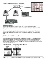
If controlling an IP controllable camera, like a AW-HE50, the camera must have a
dedicated IP address with the same subnet as the Broadcast Pix system of
192.168.53.XXX. These settings are configurable using a web browser connected to
the camera. Straight cat5 shielded cables are used for this type of installation.
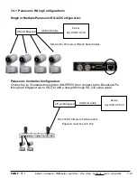
Alternatively you may control these cameras serially with the AW-CA20T6G breakout cable.
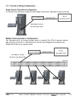
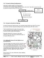
There are no COM ports out of the Broadcast Pix Server, a 4/8 port USB extender
(Edgeport) is required to control cameras serially. Panasonic PTZ cameras support star
configurations using a USB to Serial Edgeport.You may either connect 1 camera with a
RS-422 converter or have all cameras connect to the Server with several serial ports using
a star configuration. If using the USB extender (Edgeport) ensure that the port flags are set
to RS-422, as described In section 6.5.2.
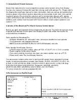
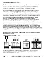
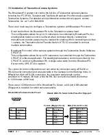
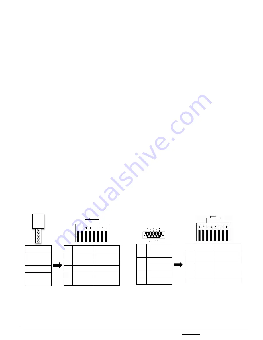
Below is the wiring diagram needed for serial cables connecting Panasonic Cameras to
Broadcast Pix COM ports.
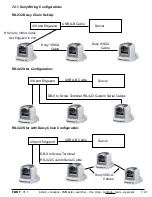
A star wiring configuration is when all camera control cables from each camera is
connect to the Server, through an Edgeport, instead of daisy chaining to each
camera. See diagrams on next page.
7.4
Function
TXD (A) -
TXD (B) +
RXD (A) -
RXD (B) +
GND
Pin Function Color
3
RXD (A) - White/Green
6
RXD (B) + Green
4
TXD (A) - Blue
5
TXD (B) + White/Blue
1
GND
White/Orange
RS-422 Terminal Connector to RJ-45 Pinout:
Pin Function
3
TXD (A) -
7
TXD (B) +
8
RXD (A) -
4
RXD (B) +
5
GND
DB 9-Pin Serial Cable to RJ-45 Pinout:
Pin Function Color
3
RXD (A) - White/Green
6
RXD (B) + Green
4
TXD (A) - Blue
5
TXD (B) + White/Blue
1
GND
White/Orange


