install - concepts - PixMaster - switcher - CG - clips - controls - team - appendix
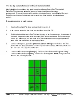
FLINT
V1.1
7.5.1 Telemetrics Wiring Configurations
Telemetrics Studio Software Configuration:
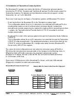
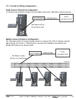
To connect Lens and other Camera Control cables, refer to the Telemetrics owners manual.
All cameras connect to the CPC-ST-S system.
7.6
DP-9 Male to Female
RS-232 Serial Cable
With Edgeport set to RS-232
CPC-ST-S
7.5.2 Telemetrics Dip Switch Settings
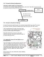
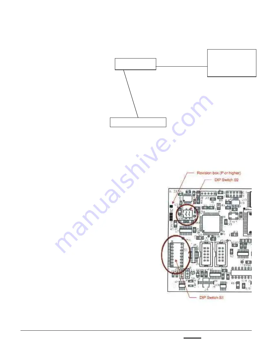
On some Telemetrics pan/tilt heads, if the controller board 53915 has a letter P or higher
as a revision number, dip switch settings must be set for RS-232 or RS-422 control.
The Controller Board is located on the same side
as the connecters on the pan/tilt head. Unscrew the
2 screws, and the board will swing open.
Dip switch labeled S2, as shown on the right,
must both be set to Off (down) for RS232 control or
On (up) for RS422 control.
7.6. Adding the Camera Control Option to an
Existing System
If you purchased your system with the Camera Control
option, the software was installed at the factory, and
so you can skip the following section. If you purchased
the camera control option after the fact, then you need
to enter the System Options Key Code, which was
supplied once you ordered the Camera Control
Option.
See section A.2 for more information about Installing
System Options.
USB A-B Cable
Server
Any USB 2.0 Port
4/8 port Edgeport

