background image

install - concepts - PixMaster - switcher - CG - clips - controls - team - appendix 

FLINT   

V1.1


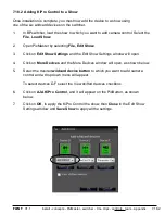
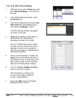
7.18.2  Adding KiPro Control to a Show 

Once installation is complete, you must now add the device to a show using  
one of the six wildcard devices on the switcher. 

1.

In BPswitcher, load the show to which you want to add camera control. Select the 

File

Load Show.


2.

Open PixMaster by selecting

 File, Edit Show. 

3.

Click on 

Edit Show Settings 

and the Edit Show Settings window will open. 

4.

Click on 

More Devices

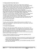
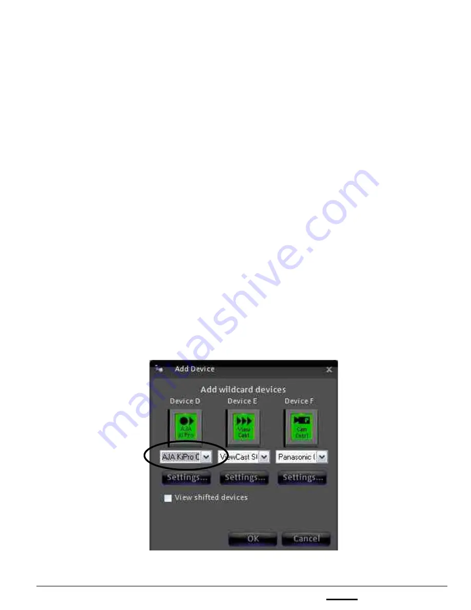
 and the More Devices window will open, as shown below. 

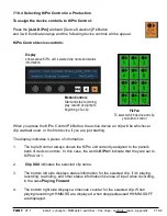
5.

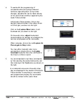
Select the desired 

wildcard device button

 to which you want to add camera 

control and a drop down menu will appear.  

 To select devices D-F select the View shifted devices checkbox. 

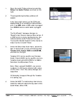
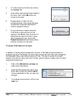
6.

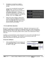
 Click on 

AJA KiPro Control

, and it will appear on the PixButton, as shown  

below. 

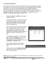
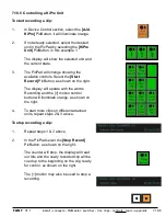
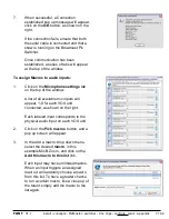
7.  

 Click on 

OK

, to apply the KiPro Control the show, then 

Close

 in the Edit Show 

Settings window and 

Save Show 

to apply all the settings.  

7.18.2 

Summary of Contents for Flint LE 1000

Page 1: ...xMaster switcher CG clips controls team appendix FLINT V1 1 Flint LE Desktop 500 1000 2000 Flint LS Desktop 500 1000 2000 Operators Manual Flint Software Version 1 1 Professional Live Produc1on with End6to6End Integra1on ...

Page 2: ...ufacturer Broadcast Pix will repair or at its sole option replace any component found to be faulty on any system returned to the service center of Broadcast Pix in the USA for repair The costs of any visit to the customer s site are not included in the warranty The cost of returning Product to Broadcast Pix is the responsibility of the end user or the Dealer Dealer is authorized to deliver the Bro...

Page 3: ... Tally GPIOs on Flint 1 5 1 Optional Tally Box 1 5 2 Installing Optional 8 port Tally Box 1 5 3 Installing Optional 24 port Tally Box 1 5 4 Installing Tally Box Drivers 1 5 5 Installing Multiple Tally Boxes 1 6 Audio I O 1 6 1 Flint LE Audio 1 6 2 Flint LS Audio 1 6 3 Clip Audio Advance 1 7 Running a Show 1 8 Flint I O Assignments 1 9 System Status 1 10 Input Timing 1 11 System Settings 1 11 1 Cha...

Page 4: ...ds 2 5 Multi View 2 5 1 Overview of the Multi View 2 5 2 Sources on Multi View 2 5 3 Keyer Windows on the Multi View 2 5 4 Program Preview Overlays on the Multi View 2 5 5 Counters 2 5 6 Switching on Multi View 2 5 7 Multi View System Settings 2 5 8 Floating Monitors 2 5 9 Labeling the Multi View 2 5 10 Multi Lingual Multi View 2 5 11 Clocks on the Multi View 2 5 12 Controlling Timer on the Multi ...

Page 5: ...ntral library 3 5 5 Manually Importing Content 3 5 6 Importing Content into a Subfolder 3 5 7 Fluent Watch Folders 3 5 8 Cloud Based Watch Folders 3 5 9 Resizing and Softening Images 3 5 10 Previewing Content 3 5 11 Renaming Content 3 5 12 Removing Content from a Show 3 5 13 Permanently Deleting Content from the Library 3 5 14 Searching for Content in the Library 3 5 15 Modifying Attributes 3 6 Sh...

Page 6: ... 4 Reversing an Effect 4 3 5 Modifying an Effect 4 3 6 Fade to Black 4 4 Keys 4 4 1 Key Controls 4 4 2 Assigning a Source to Keys 1 3 4 4 3 Direct Keys Control 4 4 4 Transitioning Keys with other keys or with the Background 4 4 5 Pro Transition Mode 4 4 6 Modifiers for Keyers 4 4 7 To Change the Key Fade Rate 4 4 8 Key Priority 4 5 DVE Boxes Picture in Picture 4 5 1 To Create a DVE Box 4 5 2 Modif...

Page 7: ...2 Recalling a Mem 4 11 3 Recalling a Mem by number 4 12 Fluent Macros 4 12 1 Opening the Macros Interface 4 12 2 Recording a Macro 4 12 3 Editing a Macro 4 12 4 Inserting Actions 4 12 5 Reviewing Macro 4 12 6 Assigning Macros in the Macro Player 4 12 7 Running Macros in the Macro Player 4 12 8 Playing back files not in shows 4 12 9 Alpha Wipes 4 13 Capture of Stills 4 13 1 To Capture an Output Ima...

Page 8: ...nd Crawls 5 4 Updating CG Graphics On the Fly 5 4 1 Quick Scribe Editing 5 4 2 Overwriting a File 5 5 Animation Store 5 5 1 Creating an Animated CG Graphic 5 5 2 Creating Animations in 3rd Party Applications 5 5 3 Basic Animation Store Operation 5 5 4 Modifiers for Animations 5 6 Basic CG Stills Operation 5 7 Preparing Still Content 5 8 Using International Characters with Inscriber 5 9 Optional Fl...

Page 9: ... 3 1 Mark In and Out Points 6 3 2 Auto Start 6 3 3 Auto Stop 6 3 4 Auto Rewind 6 3 5 Loop Clips 6 3 6 Cut Points 6 3 7 Auto Transition 6 3 8 Auto Next 6 3 9 AutoAspect Controls 6 3 10 Scrubbing a Clip 6 4 Compressed Clips 6 4 1 Exporting Compressed Clips from Final Cut Pro 6 5 Optional External DDR Control 6 5 1 Installing the External DDR Control Option 6 5 2 Verifying Installation of External DD...

Page 10: ...era Numbers for Hitachi Camera Control 7 7 4 Panasonic Camera Control Settings 7 7 5 Telemetrics Camera Control Settings 7 8 Adding Camera Control to a Show 7 9 Selecting Camera Control in a Production 7 10 Controlling a Camera Manually 7 10 1 Motion Controls for Hitachi Camera Control 7 10 2 Motion Controls for Panasonic Sony Camera Control 7 10 3 Motion Controls for Telemetrics Camera Control 7 ...

Page 11: ... in a Production 7 17 5 Controlling a Streamer Group 7 18 KiPro Control 7 18 1 Installing KiPro Control 7 18 2 Adding KiPro Control to a Show 7 18 3 KiPro Control Settings 7 18 4 Selecting KiPro Control in a Production 7 18 5 Controlling a KiPro Unit 7 19 VOX Voice Automated Production 7 19 1 Installing VOX 7 19 2 Installing the Host Override Panel 7 19 3 Installing Multiple VOX Units 7 19 4 VOX S...

Page 12: ...arate Graphics Operator and 1 Panel 8 5 2 Two Operators with Separate Graphics Operator and 2 Panels 8 6 Two Operators with Two Computers 8 7 Remote Operator in the Back Room 8 8 Dual Panels for Back Up Redundancy 8 9 Remote Control from a Distance 8 10 Remote Control from an iPhone iPod iPad Appendix A 1 Upgrading the Broadcast Pix Software A 2 Installing System Options A 3 Control Panel Internal...

Page 13: ...hich use the same BP Switcher software each with unique hardware to control the software Please refer to the Quick Start Guide for preliminary installation of your system which is included inside the Flint System box in the Open Me First envelope Flint Configurations There are 4 Flint LE configurations Flint LE Desktop Flint LE 500 Flint LE 1000 Flint LE 2000 There are 4 Flint LS configurations Fl...

Page 14: ...inputs can be at any format resolution as all video will be scaled internally to 1920x1080i Back Panel Connections 1 1 Flint Switcher 1 1 NOTE It is not recommended to have long SDI cable runs over 200 meters 655 feet for SD and 100 meters 325 feet for HD and 8 meters 25 feet for HDMI as signal quality will be degraded For longer runs it is necessary to install video amplifiers reclockers to boost...

Page 15: ...r All graphics and show files live on the Systems C hard drive and all the clips live on the Video D drive both of which are mounted internally in the system The Flint System has a 2 front doors which can be latched shut and also locked with the supplied keys in the Accessories bag The right side houses the Power and Reset switches Front Panel 1 1 1 Flint Server 1 1 1 NOTE The internal hard drive ...

Page 16: ...ort shelf or use the available sliding rack rails to provide the proper rear support when attached with multiple heavy cables The rack ears are removable to make the system fit in various equipment racks The top cover is secured with 2 side screws that unscrew completely 1 on each side and 1 rear screw that simply loosens to allow for the cover to slide off as circled below System Dimensions 1 2 F...

Page 17: ...HDMI inputs and 1 Analog 1 HDMI and 1 Stream output which simultaneously output Program 1 3 1 Flint LE System Contents The Broadcast Pix Flint LE models are comprised of the following standard components Hardware 1ME Control Panel if applicable Flint Server with I O cards installed 4 Analog Breakout cables for Analog I O DVI VGA Adaptor Inscriber USB Dongle installed internally in the Server at th...

Page 18: ...Panel 100BASE Flint LE Slot 5 Multi View 1 HDMI DVI D Multi View 2 VGA Slot 6 Slot 2 Slot 3 RCA Unbalanced Analog or HDMI Analog or HDMI Analog or HDMI Analog or HDMI Out 1 Out 1 Clip Audio Out Clip Audio Out Program HDMI Embed Program Analog RCA Unbalanced Analog Mix of Clips 1 2 RCA AES Mix of Clips 1 2 Program Stream Out Loop Out Loop Out Loop Out Same as input Same as input Same as input Cross...

Page 19: ...ed please contact Technical Support All HDMI I O is through the HDMI connectors on the I O cards please note that these are not locking HDMI connections 1 3 3 In 3 MV 1 2 Out 1 In 1 In 2 Panel In Analog Breakout HDMI In PGM Audio In Clips Audio Out HDMI Loop Out NOTE The HDMI Inputs do not accept HDCP copy protected content When using HDMI avoid going further than 25ft without using a reclocker an...

Page 20: ... SD SDI 1 Composite 1 Y C 1 HD SD Component and 1 Stream output which simultaneously output Program 1 4 1 Flint LS System Contents The Broadcast Pix Flint LS models are comprised of the following standard components Hardware 1ME Control Panel if applicable Flint Server with I O cards installed 4 BNC Female to DIN 1 0 2 3 Cable for SDI In 2 Analog Breakout cables for Analog In DVI VGA Adaptor Inscr...

Page 21: ...SD SDI Analog or HDMI Program Stream Out Loop Out Same as input Loop Out Loop Out Loop Out Loop Out Same as input Same as input Same as input Same as input RCA Unbalanced Analog or HDMI Out 1 Out 1 Out 1 Out 1 Out 1 Clip Audio Ch 1 Out PGM Audio Out Program HD SDI Embed Program SD SDI Embed Program Composite Program Y C Program Component Balanced L R Balanced L R Analog Blackburst Slot 7 Out 1 Pro...

Page 22: ...ds please note that these are not locking HDMI connections All SDI I O is through a Din 1 0 2 3 connector using the provided adaptor cable to a standard BNC female connection note that these connections do lock 1 4 3 MV 1 2 In 5 w loop out Panel In Analog Out Audio Out Ref In Breakout HDMI Out 1 PGM Audio In In 164 w loop out HD SDI Out 1 In 6 w loop out NOTE The HDMI Inputs do not accept HDCP cop...

Page 23: ...All 6 external sources plugged into the Flint Input boards can be tallied as shown by the diagram below Connectors 6 7 on the Tally Box may be used for GPOs to trigger external devices Input 1 on the Flint card corresponds to 0 on Tally Box Input 2 on the Flint card corresponds to 1 on Tally Box Input 3 on the Flint card corresponds to 2 on Tally Box Input 4 on the Flint card corresponds to 3 on T...

Page 24: ...SB ports and needs to be plugged into an electrical socket with the supplied power supply NOTE The Tally Box does not supply any voltage for tally Voltage must be provided by your Camera Control Units or other source The Tally Box only opens and closes the tally circuit Check your Camera Control Unit s user manual for more information Camera Control Unit will vary depending on manufacturer CAMERA ...

Page 25: ...lly Box to each terminal on your camera camera unit one to Program and the other to the Ground as shown below NO Normally Open goes to Program and C Common goes to Ground NC Normally Closed is not used 2 Plug in the supplied USB B to USB A cable One end in any port of the Server the other in the USB IN port of the tally box 3 Plug in the supplied power supply into Power In 9VDC port of the tally b...

Page 26: ...ctivate the drivers 1 Connect the tally box to the workstation with the supplied USB cable and plug in the power with the supplied power supply to an electrical socket 2 To confirm the installation navigate to the Start Menu All Programs Measurement Computing InstaCal This will launch the InstaCal software program as shown below left 3 Your tally box device will appear under the Universal Serial B...

Page 27: ...s 1 Ensure that the Measurement Computing InstaCal software is installed as described in section 1 5 3 and open the InstaCal software by navigating to Start Menu All Programs Measurement Computing InstaCal 2 Your tally box devices will appear under the Universal Serial Bus section as shown on the right Right click on a device and a pop up menu will appear 3 Select Change Board as shown on the righ...

Page 28: ...S systems 1 6 1 Flint LE Audio On Flint LE Systems the mixed audio output is through the Analog breakout cable and embedded in the HDMI output connected to the Output card in Slot 1 as shown below Audio out is simultaneously active on the analog output using the RCA connections labeled 12 13 AES EBU RCA connection labeled 10 and through the HDMI connection Audio out is an unbalanced line level sig...

Page 29: ...19 and the HDMI SDI streams in channels 3 4 Discreet audio out for each clip channel is also provided through the HDMI SDI embedded streams Clipstore 1 is channels 5 6 and Clipstore 2 is channels 7 8 An audio de embedder will be necessary if feeding analog audio equipment The audio input can be through the Analog breakout cable or the HDMI input connected to the second Input card in Slot 5 as show...

Page 30: ...pendently This is ideal when feeding audio equipment that can not easily control the gain of the audio or if the audio of the clip program output is too soft or too loud The digital embedded audio will not be affected by this setting Both control for these settings can be done through the Audio Tab of the System Setting window which is accessed once a show is loaded see section 1 7 1 6 3 To advanc...

Page 31: ...em Settings window will appear as shown on the bottom right 2 In System Settings window click on the Audio Tab which will bring up the various audio settings 3 In the Analog Audio Output Gain section move the sliders for the Clip Store and or Program Output The range is from 12 dB to 12 dB with the default being 0 dB 4 Click on the OK button This will close the System Settings window and the analo...

Page 32: ... show must be loaded A show is running when the Multi View is filled with content video To Run a Show 1 Double click on the Broadcast Pix Switcher application on the desktop and a Welcome Screen will appear To have the application auto start when the Server is turned on add the Broadcast Pix Switcher shortcut to the Windows Startup folder 2 The Welcome Screen is intended to configure your system t...

Page 33: ...m select the Flint Sample Show 60 or 50 Hz based on the Video Standard selected in the previous steps 7 Click on the Open button A video initialization progress window will appear please wait unit the Multi View is loaded with video this may take a few minutes Once the progress window disappears you are now ready to start using your Broadcast Pix Flint System To Change what Show is Running 1 In BP...

Page 34: ...asis This concept allows you to have custom settings for each production making for an easier setup All the inputs are multi definition and each input can have different formats attached The inputs can accept synchronous and a synchronous sources however they do no auto sense the format for each source must be selected for them to be recognized You may assign a custom name select a button icon and...

Page 35: ...cluded On LS Systems for Inputs 1 4 select HD SDI 1080i 59 94 HD SDI 1080i60 HD SDI 1080p 29 97 HD SDI 1080p30 HD SDI 720p 59 94 HD SDI 720p60 or SD SDI 486i 59 94 as shown on the right For inputs 5 6 select the appropriate format under the Format drop down menu For HDMI inputs select either HDMI 1920X108i 59 94 HDMI 1920x1080i60 HDMI 1920x1080p 29 97 HDMI 1920x1080p30 HDMI 1280x720p 59 94 HDMI 12...

Page 36: ...ton as shown on the right The Mange custom names and labels will open as shown on the right To add a custom Label select the Labels tab and enter a custom label in the text field then click on the Add Label button The custom label will appear in the white space above and may be sorted up or down the list with the arrow buttons To add a custom Name select the Names tab and enter a custom label in t...

Page 37: ...atio drop down menu Use the Aspect Correction drop down menu to select the desired treatment that will be applied when using this source in a show that has the opposite aspect ratio You may also set these settings from the control panel with Source Controls see section 4 6 9 If an audio input is being used select either Analog 14 15 or HDMI under the Audio In drop down menu as shown on the right O...

Page 38: ...Video YC requires an additional fan out cable which is also included NOTE On LE models the Analog and HDMI outputs share the same format if the Format drop down menu is set to and SD format like Composite the HDMI output will be SD 486 576i To have the HDMI output be HD set the option to 1080i Component 3 4 5 Under the SD Aspect Ratio drop down menu select either 16 9 or 4 3 Box as shown on the ri...

Page 39: ...mal operation on LS Models 1 10 System Delay All Flint Systems have low constant delay Below is a grid of the maximum total system delay in milliseconds depending on which formats are used Usually delay can be compensated in a studio environment with an audio delay Keep in mind that any audio in is appropriately delayed so that the web stream audio is in sync with the video Flints aren t designed ...

Page 40: ...d a Show as described above To change which show auto loads 1 11 1 In BPswitcher click on Setup and a drop down window will appear then select System Settings as shown on the right The System Settings window will appear as shown below 2 In the Startup Tab place a check next the to Load show at startup as show on the right 3 Select the show you want to auto load by clicking on the drop down menu an...

Page 41: ...Setup and a drop down window will appear then select System Settings as shown on the right The System Settings window will appear as shown below 2 In System Settings window click on the Video Tab which will bring up the various video settings 3 Select either the 1080i 59 94 or 1080i 50 radio button under the Video Standard section A status message will appear asking to restart the application 4 Cl...

Page 42: ... allows the user to select which frame is to be used as the first frame so the cut occurs seamlessly The default is Field 1 To change the Switching Boundary setting 1 In BPswitcher click on Setup and a drop down window will appear then select System Settings as shown on the right 2 In System Settings window click on the Video Tab which will bring up the various video settings 3 Select either the F...

Page 43: ...sically control any Flint system either through Desktop touch control iPad iPhone control Keyboard shortcuts 500 Control Panel 1000 Control Panel and or a 2000 Control Panel Below are the dimensions of the various Control Panels 500 Control Panel Dimensions Top 1 12 15 2 in 39 cm 9 3 in 24 cm 6 7 in 17 cm 1 8 in 4 5 cm 4 5 in 11 4 cm Back Side ...

Page 44: ...ip store button 1 Logo store button 1 Still store button 1 CG store button To replace a panel button 1 On the program row of the control panel gently tilt back the top edge of the key cap on the desired button 2 When the top half has popped out gently tilt the bottom edge out Be mindful that the button is now exposed watch out for any loose debris or dust getting inside the panel 3 Find the desire...

Page 45: ... panel may also be recessed into a hole cut out of a table top or console If a cut out installation is desired then the following dimensions should be used to cut the hole in the console top The panel may fit into existing cut outs for older equipment as it is the same width as a GVG100 control panel 17 5 inches 44 5 CM 11 5 8 inches 29 5 CM 4 25 inches 10 795 CM 2 inches 5 1 CM Dimensions for the...

Page 46: ...sions 1 12 Tabletop installation of control panel 7 12 in 18 08 cm 1 31 in 3 3 cm Cut out installation of control panel 0 79 in 2 cm 4 67 in 11 86 cm 26 68 in 67 77 cm 11 11 in 28 22 cm 2 45 in 6 22 cm 4 55 in 11 56 cm 27 5 in 69 85 cm Rear View Cut out Dimensions Side Views 9 5 in 23 9 cm 1 9 in 4 8 cm ...

Page 47: ...tore point It is recommended to create a restore point after your system has been installed and configured These instructions cover the basics of creating backup point and recovering to that point For advanced use of the Paragon software refer to their manual inside the Paragon software To create a back up point in Paragon 1 Quit all applications including Broadcast Pix Switcher 2 Double click the...

Page 48: ...window select the Back up now radial button and then click on the Next button 11 In the summary window click on the Next button 12 In the Completing the Backup Wizard window click on the Finish button The home screen on the application will return 13 At the top of menu bar click on the green Apply check mark button A confirmation screen will appear click on Yes as shown on the right The Overall Pr...

Page 49: ...st Pix Switcher 2 Double click the green Paragon icon on the desktop If the icon is not on the desktop navigate to The Start Menu All Programs Paragon Backup and Recovery 11 Home Paragon Backup and Recovery 3 Once the software is open click on Restore Disk or Partition button in the top left corner of the application 4 In the Welcome to the Restore Wizard screen click on the Next button 5 In the B...

Page 50: ...in this window 8 In the Restore results window ensure that the Assign the following drive letter is set C Then click on the Next button 9 In the Completing the Restore Wizard window click on the Finish button 10 At the top of menu bar click on the green Apply check mark button A confirmation screen will appear click on Yes as shown on the right The backup point will overwrite the contents of the S...

Page 51: ...ocess During the restore process a Paragon screen will appear showing the overall progress It is important not to restart or shutdown the workstation during this process as data may be lost The restore is now taking place This process will take anywhere from 20 to 40 minutes depending on the amount of files being restored 12 When the restore is complete the workstation will automatically reboot Yo...

Page 52: ...the Delete button to permanently delete the backup file The file is erased from the backup capsule Since the Backup Capsule on the System drive is only 100GB the capsule may fill up with multiple restore points Using the Desktop Shortcuts On new systems from Broadcast Pix 4 desktop icons are available as shortcuts for both creating and resorting a backup There are 2 shortcuts to create a backup Ba...

Page 53: ...gital high definition video with 3 keyers background video and a second background when transitioning Versatile Control Panels Fast action 1 Mix Effect M E control panel enables rapid control off all sources devices content and keyers Confidence of On Button Content Execute with confidence as not only the device type but th on PixButtons for every source and keyer as well as on the Multi View Pers...

Page 54: ... active in that PixButton In the illustration below the Character Generator CG is active as shown by the CG icon See Section 2 3 for all icons The remainder of the PixButton generally shows what individual content element is now active on this device in this PixButton In the illustration shown below the content number and name is shown which are the file name and number of this content element whe...

Page 55: ...sed in 5 different areas of the Broadcast Pix control panel 1 12 in the PixPad To select content within a device and for modifiers 2 9 Sources To see what is on each source and selection without preview 3 3 Direct Key To see what is in each keyer and to take it on air or off 4 3 Assignable Devices To see what is in each assignable device and to select it 5 1 Effects PixButton To see the active eff...

Page 56: ...hin a device and for modifiers 2 32 Source Displays To see what device is on each source and to modify controls 3 6 Direct Keys To see what is in each keyer and to take it on off air 4 4 Assignable Devices To see what is in each assignable device and to select it 5 1 Effects To see the active effect and to select the effects controls 6 16 Destinations To select and modify a keyer and an auxiliary ...

Page 57: ...p Store 2 Channel Instant access to clips import and play out Use motion controls and view time codes Plays compressed HD clips with embedded audio alpha channels H 264 mov mp4 ProRes DNxHD QuickTime Animation Harris Inscriber TitleMotion GS HD Character Generator 2 Channels Create broadcast quality graphics with shadows bevels transparencies logos and many more Create your own look or use easy te...

Page 58: ... external video server to be controlled from the panel through a serial connection using the VDCP Protocol having its clip name appear in the PixPad Currently 360 Systems Harris Nexio Omneon Mediadeck and Grass Valley K2 Solo Summit are supported ViewCast Streamer Control A standard feature which enables control of external ViewCast streamers encoders through TCP IP Control the starting and stoppi...

Page 59: ... controls as shown in the illustration below The remainder of the panel is comprised of the fixed controls which are described in section 4 The device controls are comprised of the Joystick up to 4 knobs up to 4 motion buttons a group of 12 buttons called the PixPad and a display as shown below When any device is selected all of these the controls are dedicated to it PixPad with 12 buttons Display...

Page 60: ...LINT V1 1 PixPad with 12 PixButtons Display Device Select 3 Axis 3 Knobs Motion Joystick Buttons 2 3 1 Device Controls portion on a 1000 Panel Device Controls portion on a 2000 Panel PixPad with 12 PixButtons 3 Axis Joystick 4 knobs 4 Motion Buttons Device Select Display ...

Page 61: ...gos are accessed by selecting the device button the 2nd channel is access by selecting Shift followed by the device button or through the Wildcard Device buttons 3 Wildcard Device A B C Buttons To control external cameras and servers For specifics on how to assign devices see section 3 7 3 3 Destination Buttons Three Key buttons 1 Effects button 1 Controls button 1 Memory button Which Device is As...

Page 62: ...ection buttons The 1st channel of CG Clips Stills and Logos are accessed by selecting the device button the 2nd channel is access by selecting Shift followed by the device button or through the Wildcard Device buttons For specifics on how to assign devices to these 3 wildcard buttons see section 3 7 3 4 Destination Buttons Three Key buttons One Source Controls button 1 Effects PixButton 1 Memory S...

Page 63: ...nt Devices The device controls are assigned to most devices by using the 7 permanent device selection buttons for CG Clips Stills and Logos 4 Wildcard Device PixButtons To control the optional camera and server control 3 Destination PixButtons 3 Key buttons 1 Effects PixButton 1 Memory Button 1 Source Control Names Memories PixButton Assigned using the Macro row of 16 PixButtons 2 3 2 ...

Page 64: ...gertips Even though you may not have a custom keyboard keyboard shortcuts can still be enabled and used on any Broadcast system with a standard keyboard 2 2 4 Enabling Keyboard Shortcuts You can enable keyboard shortcuts in one of two ways either from the keyboard or from a drop down menu in BPswitcher To enable shortcuts from the software 1 In BPswitcher select the Panel drop down menu as shown a...

Page 65: ...trol panel When any settings window other application window or when Inscriber is launched to to edit an Scribe file keyboard shortcuts will automatically be disabled in order for the keyboard to work with that application without effecting the on air video When you return to BPswitcher the keyboard will automatically be re enabled for a seamless transition To disable shortcuts Simply repeat the s...

Page 66: ...Transition Controls Off White Preview Program Source Rows Black Knobs Shift The keyboard works just like a control panel To access any shifted source or secondary function of a key simply hold down the Shift Key with the desired key To turn a knob simply hold down the desired knob key To reverse the knob hold down the Shift Key with the desired knob key When accessing any advanced features like DV...

Page 67: ...n When selected the Multi View PixPad tallies red if on air and orange if not the PixPad on the control panel will always tally red no matter if the content is on or off air use the Multi View to check tally status If a device has more than 9 content elements the next page of elements can be reached from the control panel by pressing the Next button button 12 on the control panel PixPad or by clic...

Page 68: ...concepts PixMaster switcher CG clips controls team appendix FLINT V1 1 2 4 PixPad on 500 Panel PixPad on Multi View Device Clips 1 first page in library PixPad on SoftPanel 1000 2000 Panel PixPad on Multi View ...

Page 69: ...mouse touch screen or from the control panel 9 Content Selection Buttons Buttons 1 9 on control panel To move back to previous PixPad Button 10 on control panel To move ahead to the next PixPad Button 12 on control panel To move down to the Controls PixPad Button 11 on control panel To quickly jump to the first page of the content in the PixPad simply select the device button you are using in the ...

Page 70: ...t Selection Buttons Buttons 1 9 on control panel To move back to previous PixPad Button 10 on control panel To move ahead to the next PixPad Button 12 on control panel To move down to the Controls PixPad Button 11 on control panel 2 4 1 Device Select Home Page of Multi View PixPad Status ...

Page 71: ...oystick Control for the device not available for all devices Return to the thumbnail view of the device 2 4 1 Device Select Controls Page of Multi View PixPad The control buttons below will vary from device to device For specific operation of each control refer to their section is this manual Knob Activators Knob Control Status ...

Page 72: ...ontrol is adjusted Joystick Control on the Multi View PixPad To control the Joystick select he Joystick button on the Multi View PixPad and it will highlight blue and the PixPad will show a 2 axis joystick for the X Y axis pan tilt plus a slider for the Z axis zoom as shown below Devices which use the Joystick are Keyer Controls and Camera Control Click and drag the middle circle to position the j...

Page 73: ... PixPad order window will appear 3 Use the up and down arrows to move the highlighted selection to where on the list you want it to appear Highlight other items and them move them with arrows as for the first item 4 Click OK Now the order will appear as you prepared it The top of each PixPad share the same group of 5 devices Use the forward and back error buttons to switch the next group of 5 devi...

Page 74: ...zed to virtually any size 3 Release unclick the mouse and the PixPad has been resized 2 4 3 Floating PixPads In addition to the Multi View PixPad in the top right corner of the Multi View you can create additional floating PixPads These can be used on another portion of a large screen or on dual monitor systems can be opened on a the second monitor where they are helpful as either additional info ...

Page 75: ...sists of source windows larger preview and program monitors a PixPad of thumbnails to correspond to the control panel PixPad keyer windows a status bar a clock timer clip counters as well as tally information The Multi View is also interactive so you can switch a show from the Multi View as a complement to using a panel in place of for simple shows or for backup in case the control panel loses com...

Page 76: ...iew Depending on the screen resolution the default layout may appear slightly different However the basic concepts apply to all of Multi View layouts Multi View PixPad Keyer Windows Preview Monitor Program Monitor Input Sources Clip Counters Status Bar Indicator Digital Clock 2 5 1 Menu Button Timer Countdown ...

Page 77: ...ion Thumbnail Input Name Device Name Label Content Name To view more sources above the sources shown you may create your own custom layout See section 2 5 8 2 5 2 Sources on Multi View 2 5 2 Tally Program Tally Preview Indicates Chromakey is applied hue of Chromakey Indicates Luma key is applied Source is part of a Virtual Set ...

Page 78: ...the Multi View To Manually Bring a Key On Program 1 Any key that is off air grey or orange can be brought on air by clicking on its keyer thumbnail on the Multi View This will cause this key to fade on air at the rate for that keyer and the tally underneath will change color to red To Manually Take a Key Off Program 1 Any key that is on air red can be taken off air by by clicking on its thumbnail ...

Page 79: ...e no video graphics are cut off There are 3 overlays which may be selected on Preview and or Program Title Action Safe Zones Aqua colored lines 4 3 Video Safe Zone White colored lines and Center marks Aqua colored cross To display an overlay on Preview Program 1 Right Click on the Preview or Program Monitor and a pop up menu will appear 2 At the top of the pop menu select Show safe zone Show 4 3 s...

Page 80: ...letters On Program Orange letters On Preview White letters Selected in the device store To set the clip counters to count down 1 Right click on the any counter window 2 In the pop up menu select Countdown clips as shown on the right A check mark now both counters and the counter in the display of the control panel will be set to count down To return to show the elapsed time uncheck the same settin...

Page 81: ...on the Device Tabs at the top of the PixPad To change content Click on the desired thumbnail in the PixPad To effect Preview to air Program Click on the Preview monitor Will perform the selected Mix or FX at the assigned transition rate To add a key s to Preview or to include a keyer in the next transition Click on the Trans button s To Preview a source Click on the source thumbnail and it goes to...

Page 82: ...the next transition Click on the BGR button on the bottom of the Program monitor Now only keyers with Trans enabled will be transitioned To Fade to Black Click on the FTB button on the bottom of the Program monitor The button will illuminate blue now click on the Program monitor When in black and the FTB button is illuminated red and want to fade up click on the Program monitor See section 4 3 6 f...

Page 83: ...bring up the various video settings as shown on the right 3 Deselect the Show transition controls checkbox under the Options section The Mix Fx Rate and BGR controls on the Preview and Program output monitors will now be hidden and disabled 4 Click on the OK button 5 To enable the controls repeats steps 1 4 above To modify how switching control on the Multi View 1 Open the System Settings Multi Vi...

Page 84: ...ti View tab as described in steps 1 2 above 2 Under the Options section place a check next to Preview tally green as shown on the right 3 Click on the OK button to apply the changes Now all the source monitors preview monitors and tally in the Multi View PixPad will be green as shown on the right 4 To revert back to orange tally repeat steps 1 3 above ...

Page 85: ...ke and then save them for later recall Each director producer or each show could have a custom layout tailored to that specific show You may use the default layouts as a starting point and then modify save them to your needs To create a custom layout 1 In BPswitcher click the Multi View drop down menu 2 Click on Float as shown on the right You will see the list of windows you can float Then select...

Page 86: ...tions under the Layout Colors menu as shown on the right To change the background color select the Multi View menu and select Use Colored Background by default this option is selected on To change to the color of the background select the Set Background Color option which will open a color picker as shown on the right Either select a color patch in the Web tab or select the Custom tab and choose a...

Page 87: ...select the OK button The Use Gradient option applies a subtle glow effect behind each window The Gray White Blue Font color option changes the font color of the under monitor displays on the Multi View 6 Once the Multi View has been modified to your liking it may be locked to prevent any window movement or accidental color change Select the Multi View menu then Multi View Settings and select Lock ...

Page 88: ...ut window will appear as to the right 3 Enter the name you wish to give the layout in the Layout name field You may also save layouts in different sub folders Simply click in the Layout folder field to enter the name of the folder for example Saved Layouts If no name is entered then your saved layout will appear in the main menu under the factory designed layouts 4 Click OK to save it Now it will ...

Page 89: ...rce monitor 1 Float the desired source monitor if not already open as described in section 2 5 8 2 Right click on the label name the bottom label 3 A white text box will appear enter the desired name in this example Wide Shot 4 Press the Enter key on the keyboard 5 To rename the top input name right click on the top input name and repeat steps 3 4 above All the label and input names on each copy o...

Page 90: ...l menus under the Broadcast Pix logo All labels on the Multi View i e Key and Device Names Right click contextual menus Pop up and warning messages Note to enter Unicode or Far East Languages the appropriate international fonts must be installed On Windows 7 systems they come pre installed To change the language of the Multi View 1 In BPswitcher click on the Broadcast Pix Logo menu and select the ...

Page 91: ... right 4 A grid of all the English names and labels will appear with a blank text entry under the Translation column For each line item click in the blank Translation section and Enter the translated name Note that there are multiple line items and multiple sections Use the Section drop down menu to select more groups of labels and names as shown on the right 5 Once all the text has been entered i...

Page 92: ...the drop down menu select the desired language in this example Italian To revert to the default name of a window 1 When entering a custom name it may become difficult to remember which window is being modified Right click on a label name this example will use an output window 2 A white text box will appear delete clear all the letters in the text box leaving a blank name as shown on the right 3 Pr...

Page 93: ...ay also be controlled from the panel and or Multi View PixPad as a device Multiple Analog and Digital clock may be floated however only 1 Timer can be floated To float a clock 1 Select the Multi View drop down menu 2 Select the Float option 3 Select the Clock option 4 From the available drop down menu select Analog Digital and or Timer A checkmark will appear next to the floating clocks as shown o...

Page 94: ...the countdown left click on the green play triangle button in the lower right hand corner of the timer window You may also double click in the middle of the timer to start pause the countdown 7 To stop the countdown left click on the red stop square button in the lower left hand corner of the timer window To operate a Count Up Stopwatch Timer 1 Activate the Timer window and it as Stopwatch timer a...

Page 95: ...e clock Color Changes the background face of the clock to either Blue Green Red White or Gray Offset from local time Time shifts the clock backwards or forwards both in hours and or minutes from the local time the Server is set to 5 Once customization is complete click on OK to return to the clock To save an Analog Clock 1 Float and customize an analog clock as described above right click on the c...

Page 96: ...dd Timer Control to a show 1 Select the show to which you wish to add Timer Control by loading a show or creating a new one and then opening PixMaster by selecting File Edit Show 2 Select Edit Show Settings and then More Devices See section 3 7 for more information about PixMaster and adding a device 3 In Add Device window assign the Timer Control device to a Device Button A F by selecting the dro...

Page 97: ...s 3 pieces of information 1 The top left corner always shows status running stopped and type of the timer stopwatch In this case the words Timer Countdown from 00 01 00 indicates the type of counter timer When the timer is stopped the top right of the display will show the last selected countdown time 2 The time in the bottom right of the display indicates the running time either counting up or do...

Page 98: ... will automatically start playing updating the Multi View and display The motion control button will illuminate orange signifying that the countdown is running as shown on the right To enter a custom timer 1 In Device Control section select the Timer device button A B C it will illuminate orange 2 The PixPad will change showing the available pre made timers Select the Set Time PixButton as shown o...

Page 99: ...shown on the right 3 To continue counting down from the paused time press the motion control button the button will illuminate orange 4 To reset the countdown to the start press the motion control button The countdown will stop if it was playing and reset automatically to the last countdown time used 5 When a countdown reaches the end 0 the counter has 2 modes either stop at zero or start counting...

Page 100: ...pause the stopwatch press the motion control button and the timer will stop and the button will no longer be illuminated as shown on the right 3 To continue counting up from the paused time press the motion control button the button will illuminate orange 4 To reset the stopwatch to zero press the motion control button The stopwatch will stop if it was playing and reset When the timer is set to co...

Page 101: ...ify and in the Screen Resolution section select the appropriate setting for your monitor 5 Select OK to save your changes 2 6 List of Screen Resolutions Computer monitors should always be square pixels and the display resolution should have the same ratio as the aspect of the screen The aspect of screen should never be compensated for this would distort text and images making them look too wide or...

Page 102: ...ers on the C Drive for graphics each of which corresponds to a button on the panel They are Stills C graphics stills CG C graphics cg Logos C graphics logo 3 0 D clips Show 1 Pointers to clips Show 2 Pointers to clips Show 3 Pointers to clips Etc 1 Central Clip Library Folder The D Drive The Broadcast Pix System is designed for the real time production of live shows to a live audience or recorded ...

Page 103: ...it is recommended to create a Generic Show that has all inputs sources mapped to the switcher and all devices pointed to the correct folders 3 1 To Create a New Show 1 Launch PixMaster by double clicking on the PixMaster icon on the desktop as illustrated at the right This will open the PixMaster Start Window as shown below The main Broadcast Pix Switcher application needs to be closed in order to...

Page 104: ...r as well as the content assigned to each source You can then edit from that starting point You may want to create one or more default shows as your universal starting point 4 Give the new show a name by entering it under Enter name of new show In the example shown at the right the new show name is 11pm News and its starting point is the 6PM News 5 Click on Create Show and it will open in PixMaste...

Page 105: ...ingle click on the show name and then press the Choose Show button From Switcher 1 Select the File menu as shown at the right and click on Edit Show The show that you have open with now open in PixMaster as shown in section 3 3 3 2 3 2 Selecting an Existing Show to Edit There are two ways to launch PixMaster to edit an existing show either from the desktop or from within BPswitcher From PixMaster ...

Page 106: ... memories or extra devices assigned to the 3 wildcard buttons in the upper right corner of the panel 3 View and save the content summary for the show PixMaster Show Editor 1 Click on device name button or its PixButton to edit content 2 Click here to edit the show s source assignments memories and wildcard buttons 3 Click here to view and save a content summary for the Show When done making change...

Page 107: ...u click on Clips 1 its Content Window for this show will open Content Window The content window in this case for the Clips 1 clip store enables you to Reorder the clips in the show Import new clips into this show and into the library from anywhere on your system or network Add new clips to this show from the central storage location for clips known as the clips library NOTE the location of the cli...

Page 108: ... in which it will be played out during the show again allowing for ease of use With the use of Fluent Watch folders you have the ability to automatically add clips and graphics to any show even ones that are on air This greatly enhances your workflow 3 5 1 To Reorder Content 1 Select the content you wish to move and it will highlight 2 Click on the up arrow or down arrow and the highlighted conten...

Page 109: ...old it down 3 Select the last item you wish to move and all the ones in between will highlight 4 Then click the up or down button one time for each position that you want the selected group to move In this case four adjacent clips were moved down to the bottom of the list 3 5 2 To Reorder a Group of Content In addition to moving one file up and done the list you can also move an entire group of el...

Page 110: ...he content window This will open the complete library folder that your device is pointing to as shown below To have PixMaster automatically show the entire library check the Always show entire library check box NOTE the Refresh List button is used if you edit a library using Microsoft Windows then changes made can be seen by clicking on refresh list or reopening PixMaster ...

Page 111: ...the show by clicking on the show s content list on the right side In the illustration below Hurricane is selected and so the 04 Milwaukee Weather clip will be inserted after the Hurricane clip 4 Press the forward arrow in the middle of the screen The content is now inserted into the desired position in the show A shortcut to add content into a show is double clicking with the mouse instead of usin...

Page 112: ...to move and it will highlight 2 Hold down shift on the keyboard 3 Click on the last item of the group you wish to move and it and all the ones in between will highlight 4 Then select the area in the show list into which you want to insert the selected group of clips 5 Press the forward arrow NOTE You can also select and move non contiguous material by holding down the Ctrl key while selecting indi...

Page 113: ...box is checked as shown above If you do not want this and instead just want to add it to the library but not the show then simply uncheck the box 4 Press OK A browser window opens 5 Use standard Microsoft Windows navigation to browse to the location of the clip you wish to import Select it and it will appear in the File name window 6 Press Open The clip imports Note The longer the clip is the long...

Page 114: ...fy a subfolder for this clip or group of clips then fill in its name on the blank line before you press OK This is handy for remembering a series of related clips especially when it comes time to clean excess media off your drives In this example we created a subfolder called Sample Consequently the word Sample was added in the folder column when the clip was imported ...

Page 115: ...enhances your workflow throughout your entire facility Watch Folders are show specific and each device and channel may have a watch folder enabled For any show the maximum number of watch folders that may be enabled is 8 one for Clip 1 Clip 2 Logo 1 Logo 2 CG 1 CG 2 Stills1 and Stills 2 All graphic watch folders are located in c watch and all clip watch folders are located in d watch The default f...

Page 116: ...sting files option is enabled the graphic content will update once the file is taken off air 6 Click on OK to save the Watch folder options 7 In the content window click on OK to save and enable the watch folder This will now create the enable watch folder on the C or D hard drive 8 Repeat the above steps for the remaining devices that you wish to enable Devices that are not enabled will not have ...

Page 117: ...ng Broadcast Pix double click the CurrentShow txt file The loaded show will be display as show on the right In this example 6pm News is the loaded show This text file is helpful when copying files from remote networked computers that may not be near the Broadcast Pix system This window can be closed after gathering which show is running Content may be added to any show which has watch folders enab...

Page 118: ...these secondary watch folders are show specific and each device and channel may have a watch folder enabled For any show the maximum number of secondary watch folders that may be enabled is 8 one for Clip 1 Clip 2 Logo 1 Logo 2 CG 1 CG 2 Stills1 and Stills 2 In addition this secondary Watch Folder allows any other mappable network folder to become a watch folder This is useful for having a screeni...

Page 119: ...ydrive navigate to C Users Broadcast Pix then select the Dropbox Skydrive or Google Drive subfolder This example will use Dropbox NOTE For the Dropbox Skydrive of Google Drive folder to appear you must have at least one of these services installed on the Broadcast Pix Server and registered with an account to one of those service providers It may also be convenient to create a subfolder on your sto...

Page 120: ...tent folder on the local Broadcast Pix Server Please refer to the individual service providers on how to upload content using their application This allows you to upload content from any web browser from any device from anywhere in the world And for many providers a mobile application can be installed on an iPhone or Android device which provides instant access to your Watch Folders In addition si...

Page 121: ...fore see section 3 5 5 3 5 9 3 5 9 Resizing and Softening Images When content is imported it can either come in as is or the images can be resized and softened upon import This is particularly useful when you are treating graphic images such as PowerPoint slides for video presentation or when importing photos from a digital camera NOTE When the Resize and Soften function is selected the file s wil...

Page 122: ...ng previewed click on the X in its upper right corner 3 5 10 3 5 10 Previewing Content At any time you can see a large thumbnail of any content element in any device This is handy if the filename doesn t represent what the content is and you would like to verify if the content is correct All thumbnails are still images the thumbnail for a clip or animation will show you the first frame of video In...

Page 123: ... This may take several seconds depending on much much content is stored on the system Once complete the grid of content will show a thumbnail for all valid files as shown below 2 When you close out of each store re enter each store to edit content this option much be rechecked as it is not remembered 3 5 10 NOTE If no Preview is shown then a thumbnail needs to created for that clip see section 6 1...

Page 124: ... Library button 2 Select the item you wish to rename in the Entire Library section of the window 3 Right click on the file and a drop down menu will appear with 3 options as shown below 4 Select on Rename and a rename file window will appear as shown below 5 Enter the desired name and click on OK If a number is placed in front of the file also known as a leading number for example 02 Light Swipe b...

Page 125: ...ry as removing a content does not delete it from your system If you want to delete content from the hard drive see section 3 5 12 3 5 12 6 If leadings numbers are being used on content you have the option to not view the number on the PixButton When active this option allows for more characters to be used on the PixButton instead of space being taken up by numbers However the number will still app...

Page 126: ...ed and it is not recommended To Delete a Clip or Graphic from the Library 1 Make sure your are viewing the entire library by clicking on the View entire library button and the content window will expand to show the library 2 Right click on the item you wish to delete and a drop down menu with 3 options will appear as shown below 3 Click on the word Delete and a window will pop up to ask to confirm...

Page 127: ...ntire library button as shown on the right 2 In the search bar at the top of the window type in a search word As you type the grid on content will filter out content and show you content that only matches your search as shown on the right 3 To search just the beginning of the file name and not the entire filename select the Start with text checkbox 4 To view all the content of the library delete t...

Page 128: ...n to expose more options 2 For every piece of content there is a checkbox for every attribute allowing you to easily see which attributes are active in addition to easily modifying them To change an attribute simply check or uncheck the desired attribute 3 To turn a specific attribute on or off for ALL content click on the first check box at the top of the grid under each attribute label as shown ...

Page 129: ...Content Summary On the PixMaster window for the desired show click on View show contents The View Show Contents window will open To Save the Content Summary You can save this by clicking on Save List It is saved as a text delineated file which can then be opened in columns with a program like excel To Print the Content Summary If you have a printer installed on your system you can print the list b...

Page 130: ... the Settings Windows for the Show will appear The Show Settings window enables you to edit Switcher Sources for re mapping adding and removing sources as well as assigning a fail safe source More Devices for assigning devices to the three wildcard PixButtons i e camera control Memories for adding removing sorting and naming SnapShot Macro Memories Memory Rows for assigning SnapShot and Macro Memo...

Page 131: ...ill open showing all 18 32 on a 2000 panel mapable input sources 2 Select the source number you wish to change by clicking on its name A drop down menu will appear with all your available source names created in the Flint Input Assignments window in addition to all the internal clip and graphic channels 3 Select the desired name to map to the control panel 4 Click on OK when complete 3 7 1 NOTE Th...

Page 132: ... Show Settings window To remove a wildcard device 1 Repeat steps 1 2 above 2 Select remove from the drop down list 3 Click on OK to return to the Edit Show Settings window 3 7 2 Adding Wildcard Devices The Broadcast Pix system has four standard content devices with four dedicated control panel buttons Clips ch 1 Stills ch 1 CG ch 1 and Logo ch 1 In addition Clips ch 2 Logo ch 2 Stills ch 2 and CG ...

Page 133: ...cros may also be added and sorted in this menu if a Macro has a leading number applied to it See section 4 12 for more information about Macros The memory controls in PixMaster enable you to Note The third item is a global change affecting all shows so whatever name and image you choose will be used in all shows for this memory To access show memory controls on the Show Settings window click on Me...

Page 134: ...dow click on View all memories which will expand the memory window to include the central library of all memories For moving memories into a show and organizing them this window works same way as the clip or still content window see section 3 5 The only difference here is that as you select each memory you can see its PixButton in the upper right corner ...

Page 135: ...the expanded Memory window shown on the previous page 2 Click on Edit memory The Edit Memory window opens 3 Fill in the name you wish to give the Memory in the Name for memory x field 4 If you leave the Use name on PixButton box checked the name you entered will be put on the PixButton and displayed as such on the switcher panel As you type a name the PixButton icon will update automatically to sh...

Page 136: ... the text with the 2 arrows and the position will show in the white preview window It is recommended to use the default font if desired you may select another by un checking the Use default font box 4 Select Apply and the text will appear in the big green window which represents the PixButton 5 If desired you may draw custom icons on the button by left clicking with the mouse and dragging Custom i...

Page 137: ...r triggering Alpha Wipe transitions and other frequently used effects without having the need to enter the MEM Device PixPad To assign MEMs to the Memory Rows 1 In the Edit Show Settings window select the gray Memory rows button The Memory row organizer window will appear as shown 2 Click on the desired button to assign a Snapshot or Macro Memory To assign a memory to buttons 17 32 click on the Vi...

Page 138: ...s option will continue to show the source name icon when in the memory mode 6 To view source names icons on unassigned memory buttons place a check mark next to Show source names on unassigned buttons Selecting this option will show a mix of memory icons and sources icons when in the memory mode 7 To apply these changes to the Memory row click on OK This will close the Memory row organizer window ...

Page 139: ... only available when the optional external tally box is installed as described in section 1 4 2 Since this is an advanced feature in large installations it is advised to contact Technical Support regarding any questions To Remap Tally Outputs 1 Open PixMaster to its first editable screen Select a device to edit as shown below 2 Select the Remap Tallies button and the remap tallies window will appe...

Page 140: ...ro pre saved recorded to be available as a selection To Link a Layout to a Show 3 9 1 Open PixMaster to its first editable screen the Select a device to edit as shown to the right 2 Place a check mark next to the Load layout with show 3 Click on the Load layout with show drop down menu and select the desired saved layout from the available list as shown on the right To save a layout to appear in t...

Page 141: ...wn to the right 2 Place a check mark next to the Load memory with show 3 Click on the Load memory with show drop down menu and select the desired saved SnapShot Memory or Macro from the available list as shown on the right To save a Macro or MEM see section 4 12 On the next show load the selected memory macro will run 4 To have no memory load at show load uncheck the Load memory with show option ...

Page 142: ...om the Multi View see section 2 5 6 4 0 Switcher Controls When you launch Broadcast Pix Switcher and a show is loaded see section 1 6 the switcher controls fill in on the panel as shown below Source Controls To select sources for bringing on air as backgrounds or key overlays And for filling keys and auxiliary outputs Transition Controls To change what is on program with a cut mix or effect Direct...

Page 143: ...he optional tally box is installed the program tally is also sent out Panel Tally State Color Buttons PixButtons Selected and on Program Red Selected and on PreviewOrange Off not selected White buttons Green PixButtons Selected and on Program Red Selected and on PreviewOrange Off not selected Grey None 4 0 1 NOTE There is not tally status in the PixPad of the control panel Red simply means that th...

Page 144: ...the control panel as illustrated below These 9 sources are arrayed in columns of 3 buttons each The same source is assigned to all three buttons in each column The displays on the PixButtons in the program row indicate what source and content element is currently assigned to that column of buttons Within any one row only one source may be selected at once Therefore only one button in the source or...

Page 145: ...not be illuminated Preview Row The Preview Row is used to select which source is selected on preview preset which will be illuminated orange during a transition the preview row illuminates red and returns to orange at the end of the transition Source Row The Source Row is used to select which source is used to fill a key or an auxiliary output sources will be illuminated orange to signify that the...

Page 146: ...to the names of sources 10 18 There is no need to hold down shift since the panel will stay in the shifted state until it is deselected 2 Select a button from the Program Preview or Source rows as desired The selected button will illuminate To indicate that this button is in a shifted state on the SoftPanel a small light above it will illuminate while on the Control panel the button will blink 3 P...

Page 147: ...es more rapidly without the need of selecting shift every time for these occasions the shift function may be locked To turn on Lock Shift from the control panel 1 Double punch the Shift button quickly select it 2 times The Shift button will illuminate orange To turn on Lock Shift from the application 1 In BPswitcher select the Panel drop down menu 2 Select Panel Settings 3 Click on Lock Shift to p...

Page 148: ...change to the names of sources 10 18 There is no need to hold down shift since the panel will stay in the shifted state until it is deselected 2 Select a button from the Program Preview or Source rows as desired The selected button will illuminate To indicate that this button is in a shifted state on the SoftPanel a small light above it will illuminate while on the Control panel the button will bl...

Page 149: ... which one picture dissolves into the next Effect An effect is a transition that uses a pattern or special effect to transition from one picture to the next Effects include wipes pushes squeezes and other 2D DVE moves The transition section of the control panel manages all transitions It is illustrated below along with the function of each area of its controls Cut Auto Key 1 Bgr Mix Key 2 Key 3 To...

Page 150: ... press Bgr and it will illuminate orange 2 On the preview bus select the source you wish to transition to by pressing its button The button will light orange and the selected source is displayed in the preview monitor In this example the clip store is on preview and Cam 2 on program 3 Press the Cut transition button This will bring the selected source to program and whatever was on program to the ...

Page 151: ...is displayed in the preview monitor 3 If not already lit press the Mix button which will illuminate orange The effects PixButton to the right of it will change to green 4 Press the Auto Trans button This will bring the selected source to program and whatever was on program to the preview monitor The illuminated buttons will also flip flop on the program and preview rows During the transition the c...

Page 152: ...evice Controls will change to effect including the PixPad knobs and joystick The effect that is currently selected and ready to execute is shown in the effects PixButton in the transition section its corresponding button in the PixPad is also illuminated orange and its name is shown in the display 4 Press the Auto Trans button This will bring the selected source to program using the selected trans...

Page 153: ...tton This will cause the following device controls to appear 3 Knobs for modifying effects LED Display shows selected device effect knob values and numeric keypad value Effects Device Controls Effects PixButton to turn on Effects Device Controls and show which effect is selected PixPad 12 PixButtons to select or modify an effect Effects Fx 01 Vertical Wipe Rate Trate 30 2 The Effects PixPad displa...

Page 154: ...r 4 To see the 9 beyond that press the Next PixButton again You may press the Next button until the PixPad runs out of assigned pages 5 To back up and look at the previous PixPad press the Back PixButton 6 To return the the home or first page of the Effect PixPad press the Effects PixButton 4 3 Multi View PixPad 12 Buttons to select view or modify an effect ...

Page 155: ...so be reversed see section 4 3 5 Types of Transition Effects The Broadcast Pix Switcher supports many types of transitions each has its own style PixButton icon For example if there was currently a picture of the sun on air background and you wish to transition to a person foreground Foreground Background Example PixButton 1 Wipes Both Images stay in place and one is wiped over the other 2 Pushed ...

Page 156: ...ipes which start in one position and then move in a circle Their icons show a black region where the foreground begins to enter and then a curved or diagonal arrow with the direction of the clock movement For example clock wipe Fx 115 has the following icon and creates the illustrated effect An arc wipe is similar to a clock wipe except that the movement is in a much wider arc in which the center ...

Page 157: ...umber you wish using the numeric keypad As you enter each number it will appear in the display For example Fx 122 as shown below If you enter a wrong number press the UP PixButton which will bring back to the previous PixPad where you can start again from step 2 4 Press the Enter PixButton and the effect will appear in the Effects PixButton and its name and number will also appear in the display T...

Page 158: ... in frames with 30 frames being equal to one second in 60Hz and 25 being equal to one second in 50Hz The system defaults to 30 frames until another rate is selected To change the transition rate with a knob 1 If the Device Controls are not already assigned to effects press the Effects PixButton in the transition section and the display illustrated below will appear 2 Turn the 1ST Knob to the desir...

Page 159: ... OR 1 If the Device Controls are not already assigned to effects press the Effects PixButton 3 Press the Trans Rate PixButton and the following numeric keypad will appear 4 Enter the rate Number you wish using the numeric keypad As you enter each number it will appear in the display If you enter a wrong number press the UP PixButton and repeat step 3 5 Press the Enter PixButton and the rate will a...

Page 160: ...tart on the outside and go to the center etc To reverse an effect To Reverse the direction of all effects on the Effects PixPad press the Controls PixButton then press the Reverse PixButton To indicate that Reverse has been selected the letter R will be appended to every effect name in the display as shown below To remove reverse and return to the normal state press the Reverse PixButton again and...

Page 161: ...ffects if they are not press the Effects PixButton in the transition section 3 Select the effect you want with either the numeric keypad or one of the Effect Pattern PixButtons 4 Click the Controls PixButton for a selected transition to modify the softness aspect and transition rates 5 To see a transition effect in pre production move the Fader Arm half way 6 To change the softness of the edge of ...

Page 162: ...n the Program monitor it will illuminate blue as shown on the right 3 The PixPad will change showing a numeric keypad as shown on the right Enter the desired fade to black rate with the Numbers PixButtons As you enter each number it will appear in the display The rate is in frames with 30 being 1 second for 60Hz systems and 25 form 50Hz systems 4 Press the Enter PixButton 5 Click on the Program mo...

Page 163: ...uminate amber 2 Press on the Controls PixButton in the FX PixPad as shown on the right 3 Press the FTB Rate PixButton and a numeric pad will appear 4 Enter the desired fade to black rate with the Numbers PixButtons As you enter each number it will appear in the display 5 Press the Enter PixButton To execute FTB on a 500 or 2000 panel 1 Press the FTB button in the transitions section as shown on th...

Page 164: ...raphic such as a CG Still or Logo or a DVE box Picture in Picture which can hold a camera still clip or any other source Any key may hold a Chroma Luma Key however only one source at a time may have a Chroma Luma key applied as an option multiple sources can have Chromakey Luma keys controls useful for virtual sets In the example below the composition includes four layers Composited Picture Key 3 ...

Page 165: ...controls to that Key including Joystick 3 or 4 knobs PixPad and the Display In addition all six keys are also shown graphically and in full motion on the Multi View for feedback Key 1 Key 2 Key 3 Key 3 Key 1 Key 2 Direct Key Buttons Key Transition Buttons For including keys in transitions Also previews a key Source Row For use with the Key Select Buttons to change which device is assigned to a key...

Page 166: ...s not on air If a shifted source 10 18 is currently in the key it will blink on the Control panel and illuminate a small light above the button on the SoftPanel 4 4 2 Assigning a Source to Key 1 3 Each of the three keys may hold a variety of sources including a cg animation still a DVE box picture in picture window for camera etc Each source is assigned to Key 1 2 and 3 by using the Key Selection ...

Page 167: ...ottom right corner of the panel This will cause this key such as the still in key 2 in the above example to fade on at the rate for that keyer and the button will change color to red To Manually Take a Key Off Program 1 Any key that is on air red can be taken off program by pressing its Direct Key Button in the bottom right corner of the panel This will cause this key such as the title in key 3 in...

Page 168: ... Transition buttons is pressed its corresponding Direct Key button in the lower right corner of the panel will change from green to orange 3 Press Cut or Auto or use the fader arm and the background video will change the illuminated keys will come on program and their Direct Key buttons in the lower right corner of the panel will change illumination from orange to red In the above example two keys...

Page 169: ...ition section of the control panel by default the buttons layers are added selected one at a time leaving the previously selected layers enabled For most users this method is acceptable however in some cases where rapid execution is necessary users may prefer to only have the selected layer active disabling the previously select layers This mode is known as Pro Transition Mode Key 1 Bgr Key 2 Key ...

Page 170: ... left crop the 2nd Knob to just crop the top and 3rd Knob to change which of the four corners to crop from LeftTop shown to LeftBot RightTop and RightBot Once any side has been cropped the display and keyer window on the Multi View will read out Cr next to the key rate signifying cropping has been applied You can reset the cropping to none 000 by pressing the Crop Reset button in the Keyer Modifie...

Page 171: ...X Axis control and or the 2nd Knob for Y Axis control using the knobs provides fine tuned control For quicker control the Joystick may also be used Move the Joystick Once a keyer has be repositioned the display and Keyer window on the Multi View will read out Rp next to the key rate You can reset the position to 0 0 by pressing the Posit Reset button in the Keyer Modifier PixPad Or when no DVE is ...

Page 172: ...fade rate 1 Press the Key Select button for the desired keyer to assign the Device Controls to that key 2 Turn the left knob to the desired transition rate which will be shown after the letters Ra in the display above the knob or Press the Key Rate PixButton on the Key PixPad for the desired Key enter the rate with the numeric keypad as done for a transition rate and press Enter to apply the rate ...

Page 173: ...allows you to change the layer order of the keyers by bringing a key layer up towards the foreground or down towards the background This is useful when creating DVE boxes see next section and want to zoom a keyer full screen over another It is also useful in compositing graphics and boxes without the need to reassign sources to different keyers The Key Priority is controlled from the PixPad with t...

Page 174: ...he destination row it will illuminate orange The PixPad will change showing the controls for the keyer 2 Select the Layer Down PixButton as shown on the right The keyer will move up one layer and the display will update to reflect that as shown on the right 3 To move the same keyer up more layers continue to select the Layer Down PixButton 4 To move a different keyer up one layer repeat steps 1 2 ...

Page 175: ...gn the Device Controls to the Keyer selected as described in section 4 4 2 3 Press the DVE OnOff PixButton on the PixPad which will cause the word DVE to appear in the display to let you know the DVE is applied as shown below Key1 Ra1 DVE Rate 4 5 DVE Boxes Picture in Picture All 3 Keyers may have a DVE Digital Video Effect Box otherwise known as a Picture in Picture applied to it In television ne...

Page 176: ...appear on the preview monitor 6 You can change which source you would like to feed into the DVE Box by pressing another Source button in the source row When pressed the content will appear in the DVE Box on the preview monitor 7 Bring the previewed DVE Box to air by pressing either the Cut or Auto buttons or using the Fader Arm or you can manually bring the DVE Box to air by pressing its Direct Ke...

Page 177: ...the desired DVE Box on the preview monitor by executing steps 1 through 5 above in section 4 5 1 1 The position of the DVE Box may be modified by using the Joystick as follows 2 The size of the DVE Box may be modified by twisting the Joystick or The size may also be changed by pressing the Size PixButton and then twisting the left knob for overall size and the center knob and right knob to individ...

Page 178: ...n Blue Turn the corresponding knobs until the desired color is reached 4 5 3 4 5 3 Multiple DVE Boxes Two DVE Boxes may be used at once one on Key 1 and the other on Key 2 This is known as dual boxes or a Split back as shown below To create dual boxes set one of them up on Key 1 as described above and then set up another on Key 2 in the same way In the same way six DVE Boxes can also be created by...

Page 179: ...r that source is outputted to it will have the associated source controls applied to it To activate source controls 1 Select the Controls button in the Destination Row on the control panel or SoftPanel and it will illuminate 2 The display will read out which source is selected and the source row will have its button illuminated To effect modify another source select any mapped source on the switch...

Page 180: ...e as shown below 3 Select the native aspect ratio of the source either Native 4 3 or Native 16 9 in the PixPad 4 Now select the desired treatment effect either Auto Asp Box Auto Asp 14 9 or Auto Asp Crop NOTE that the Multi View source monitors will only show the native aspect ratio 16 9 or 4 3 boxed whereas the Multi View Preview and Program monitors will also show the applied treatment 4 6 Exter...

Page 181: ...the source either Native 4 3 or Native 16 9 in the PixPad 4 Now select the desired treatment effect either Auto Asp Box Auto Asp 14 9 or Auto Asp Crop Note that the Multi View source monitors will only show the native aspect ratio 16 9 or 4 3 boxed whereas the Multi View Preview and Program monitors will also show the applied treatment The Animation store does not have any Aspect Controls since al...

Page 182: ... may have chromakey applies to them The most important element to a successful Chromakey is even lighting Not only do you need to light your subject with standard 3 point lighting Key Fill Back light it is also important to evenly light your Chromakey wall the background of the subject Once that is accomplished you are now ready to use the Chromakey feature 4 7 1 Activating the Chromakey 1 Place t...

Page 183: ...ed on 5 Press the Chrma Cntrls button on the above PixPad to bring up the Chromakey controls on the PixPad as shown below The Chrma Cntrls button will not bring up these controls unless you have turned the Chromakey on as described in step 4 6 To select the default settings for Blue or Green Chromakey select either the Key Blue or Key Green in the above PixPad This will activate the factory settin...

Page 184: ...heel in degrees Outside of the acceptance angle is opaque within has increasing transparency as you approach the exact hue The wider the angle the more colors are accepted as transparent 0 to 180 Clip Clp Represents offset of the wedge of the color being selected Negative towards higher saturation positive towards opposite side of the color wheel Useful when dark objects are becoming fully transpa...

Page 185: ...he colored edge around your subject is mostly keyed out 5 Press the Clip Shrink Spill PixButton in the Chrma Cntrls PixPad 6 Adjust the Clp value to reduce the amount of your background that is remaining This value should be around 0 plus or minus a few degrees Too much clip will cause your subject to be transparent 7 If needed you may shrink the edges of your subject by adjusting the Shr value 8 ...

Page 186: ...g a Luma key all controls are accessed through the Source Controls PixPad Also when a Luma key is applied to a source the Luma key will appear everywhere that source is applied to i e program preview key etc 4 8 1 Activating Adjusting the Luma key 1 Place the source which is to be Luma keyed in a Key by pressing the Key Select button of that key in the destination row and then the source button fo...

Page 187: ... Adjust the Gain value by turning its knob under the display The Gain setting determines the overall amount of brightness that is cut out The greater amount of gain the harsher the edges will be too much gain will make the entire source transparent 7 To invert the keying press the Luma Cntrls button on the Source Controls PixPad to bring up the Luma Key controls on the PixPad as shown below The Lu...

Page 188: ...lect the desired input to modify by clicking on the Source pull down menu This example will use Input 3 Any external or internal source may be selected however only external sources and clips may have a chroma or luma keyer assigned 3 To turn on the Chromakey click on the Chromakey button and it will illuminate blue this will turn on the chromakey for this input and the available chromakey setting...

Page 189: ...Store button as shown on the right In the Adjust settings pull down menu select a different input and click on the Recall button Now all the values from the previous input are copied to this newly selected input To adjust Lumakey controls 1 Repeat steps 1 through 3 above by opening the Fluent Controls windows 2 Click on the Lumakey button and it will illuminate blue as shown on the right 3 To modi...

Page 190: ...red as all Flint Systems process video at 16 9 For more information about AutoAspect see section 1 8 1 To select content 1 When any internal source is selected i e Clips Anim CG or Stills so too can a specific piece of content be selected In the Source drop down menu select Clips1 Clips2 Logo1 Logo2 CG1 CG2 Stills1 or Stills2 as shown on the right 2 Two navigational buttons will appear as well as ...

Page 191: ...put into the switcher Virtual Sets is a global attribute which applies to all shows To activate angles 4 9 1 1 Open the Fluent Controls window by selecting the Panel Fluent Controls menu from the Broadcast Pix menu button as shown on the right 2 Along the left edge of the Fluent Control window select the Virtual Sets button it will illuminate blue as shown of the right 3 The top section labeled An...

Page 192: ...put to an angle click on the Assign button on the bottom of the thumbnail and a pop up window will appear as shown on the right 6 In the Assign Angle Source window select which switcher input 1 8 Clip 1 or Clip 2 will be used as shown on the right 7 Click on the OK button The source is now married with an angle ...

Page 193: ...et background see section 4 9 2 5 stock sets are provided with each system users may add or remove to this list using standard Windows conventions of copy paste save 2 Select the folder of images to browse using the mouse in this example Colored Blocks 3 The Images pane will update showing you thumbnails of all the files in the folder as shown on the right To change the size of these thumbnails cl...

Page 194: ...of the selected angle double click on the angle thumbnail and the Images pane will change as shown on the right with Angle 1 To adjust the chromakey settings 1 Once a background has been assigned to an angle all chromakey control can be modified from the control panel or Input Settings of the Fluent Controls window as described in sections 4 7 4 9 2 Selecting the desired angle to modify in the Vir...

Page 195: ...number to use either 1 2 3 4 5 or 6 by selecting the corresponding radio button Enter a button caption in the Caption text field as shown on the right 3 Click on the Save button Now each background for each Angle has been saved No source assignment or Chromakey settings are saved simply the background assignment 4 To save other presets repeat steps 1 3 above Recalling a Preset 1 To recall a Virtua...

Page 196: ...basic photo enhancements are included like brightness contrast and blur to give the right depth of field to your Virtual Set To import an image 1 Open the Fluent Controls window if not already open by selecting the Panel Fluent Controls menu 2 Click on the Image Editor button and it will highlight blue as shown on the right 3 On the bottom left edge of the Image pane click on the Import Image butt...

Page 197: ...and drag anywhere on the original image 3 In the middle of the Image Editor there are basic controls to modify the picture Move the sliders to the right to increase the Brightness Contrast Gamma Blur The blur slider is useful to add the correct amount of depth of field to your image Move them to the left to decrease 4 Clicking on the individual label i e Brighten will reset the value and remove th...

Page 198: ...d Angle back to the assigned image Exporting an image 1 Once the image is modified to your liking the file can be exported for use in the Images section of the Virtual Set or the still store of the switcher for use as a background In the Output Image section click on the Save Image button as shown on the right 2 A Windows Save as window will appear navigate to C graphics Virtual Sets and either cr...

Page 199: ...utput 4 11 1 Remote Panel Wiring The Remote Panel Flint Server and Control Panel all must be on the same network using a Network Switch using standard straight through Cat5e cables The Remote Panels fit into a standard 19 rack with the integrated rack ears which are not removable Wire the Remote Panel s as described below 1 Connect the Remote Panel s to a Network Switch using the To Switcher conne...

Page 200: ...Address 1 On the Remote Panel select and hold down the Shift button it will illuminate yellow Then select the Lock button as shown below This will put the Remote Panel into an offline setup mode as shown below 2 Press the 2 input PixButton labeled Panel IP and the PixButtons will change showing the assigned IP address as shown below 3 Press the 10 11 and or A input PixButtons to enter the desired ...

Page 201: ...xit out of the setup function 6 Click on the Output PixButton labeled Join The Show to connect to a running show To Change the Button Contrast 1 On the Remote Panel select and hold down the Shift button it will illuminate yellow Then select the Lock button 2 This will put the Remote Panel into an offline setup mode as shown below 3 Press the 4 input PixButton labeled Set Black and the PixButtons w...

Page 202: ...e in PixMaster Show Editor and every setting is show based meaning that all the settings are saved and recalled on a show by show basis To Setup the Remote Panels 1 Launch BPswitcher and load a show as described in section 1 6 2 Click on the Broadcast Pix Menu and select File Edit Show as shown on the right 3 In the PixMaster window select the Remote Panels button as shown on the right This will o...

Page 203: ...rrent state of the mode In the Switcher Inputs section click on the input to enable or disable 1 through 6 the PixButtons will update to Grey or Green as shown to the right Grey PixButtons signify that the input or output is blocked and not accessible from the Remote Panel Green PixButtons signify that the input or output is allowed for selection The inputs shown are the direct inputs to the Flint...

Page 204: ...e desired memory and click on the Assign to Button button The assign window will close and the PixButton will update showing the number and or custom name as shown on the right To view assign memories 12 22 click on the Shift button as shown on the right To un assign a memory click on an assigned memory button and in the Assign memory window click on the Unassign Memory button The PixButton will n...

Page 205: ...e showing the Modes 1 11 and an Exit button as shown below 3 Select the desired Mode PixButton 1 through 11 to access modes 12 22 select the Shift button The Remote Panel will automatically connect to a running show with the newly selected mode To Lock the Remote Panel 1 On the Remote Panel select the Lock button it will illuminate red as shown on the right Now any button push will be ignored by t...

Page 206: ...on The Macro PixButton will illuminate red and the B PixButton will illuminate orange and turn to a Play icon 4 To stop running a macro re select the macro SnapShot PixButton or select the A input PixButton with the orange Stop icon The memory PixButton will return to a green not selected state 5 To access memories 12 22 select the Shift button it will illuminate yellow as shown on the right Repea...

Page 207: ...rt are generally saved during pre production before a show is on air The saving process takes several steps to indicate exactly which portions of the panel to save and whether to save just the set ups or the source assignments as well In contrast since the recalls of memories happen on air recall is streamlined and designed to be quickly accessible There are a total of 999 global memories which ca...

Page 208: ... press each the display will keep track of them so you know what you saved For example to save key 1 press the Mem Save Key 1 PixButton Press it once for the key set up and the display will say 1k For example a DVE box set up Press it again to save both key set up and the source number assigned to it and the display will say 1s For example a DVE box set up plus which source number to fill it with ...

Page 209: ... will save the preview source press again to save the content Pv or Pvc Mem Save Prog PixButton will save the program source press again to save the content Pg or Pgc Mem Save Trans PixButton will save the transition selected as well as any modifiers including softness aspect and rate If you press it again it will also save the state of the Bgr and key transition buttons T or T Mem Sav More PixBut...

Page 210: ...utton is a short cut for saving Direct Keys 1 to 3 Press again and it clears all 3 Direct Keys from the display D123 or blank Mem Recall Rate PixButton sets the amount of time in frames a memory will take to be recalled during a production Useful for creating on air DVE moves for push back animations Mem Save All PixButton saves the state of all the devices on the control panel Press it again and ...

Page 211: ...tion is not available on a Flint System When finished press the Up Arrow to return to this PixPad see below 10 Once all your options are selected on the main Mem controls PixPad press Save MEM If the main Mem PixPad is not visible press the UP PixButton until it is visible Once select the display will read out that your memory is saved similar to as shown below Main Mem PixPad ...

Page 212: ... the memory number and it s attributes plus the Status Bar on the Multi View will display which SnapShot MEM was recalled 4 11 3 To recall a Mem by number 1 Press the Mem device and the MEM PixPad will appear 2 Press the Controls PixButton 3 Then in the following PixPad select the Numeric keypad PixButton 4 Enter the number of the desired MEM in the number PixPad 5 Press the Enter PixButton to rec...

Page 213: ...r pre made effects Macro Editor Overview Action List Displays the list of commands steps in a selected macro Fields include Time to show duration Hold time to show how many frames a specific action will take to start a Note field for user comments and Action to view the command Menu Contains the available settings for Macros Toolbar Contains the available options to to open and save a macro Title ...

Page 214: ... trigger Up to 100 macros per bank can be assigned Counter Displays the running elapsed time of the active macro Display Shows the active macro file name and status information Details Panel Shows user notes that were saved within the Note field of a Macro Control Bar Contains the available tools to playback control a macro 4 12 1 Opening the Macros interface The Fluent Macros window can be launch...

Page 215: ...3 To record a macro from the Macro Editor 1 Open the Macro window as described in section 4 12 1 2 If the Action List is blank proceed to step 3 if not click on the New button in the Toolbar as shown on the right or click on the Menu and select New 3 Click on the Record button in the Macro Control Bar Macros is now waiting for the first panel operation to occur for the timer to start The Record bu...

Page 216: ...o save the recorded macro onto the hard drive Enter a name and click on Save All macros will have a tln file extension and all SnapShot Mems have a bpm file extension In order for Macros to be stored and recalled in the MEM device of the control panel a 3 digit number must be added to the front of the file name i e 123 Swipe tln but may not have the same number as a bpm file There are a total of 9...

Page 217: ...ro is recording the counter in the lower right corner will start to move and the Play motion control button will illuminate red 7 When the macro is finished being recorded select the MEM device button it will illuminate orange 8 Select the Back motion control button to stop the recording as shown on the right The Play motion control button will turn off and the display will read out Recording ende...

Page 218: ...p will highlight white and the Details Panel will display the editable fields of that command each command will have slightly different panel 2 Modify the top timing information in the Details Panel The top portion of the Panel is the same for every command as shown on the right Non editable command name which appears in the Action field of the Action list Editable Note field which appears in the ...

Page 219: ...drop down menu Content selector displays a thumbnail and address bar for changing which clip or graphic is loaded in a specified store To select a different clip or graphic click on the Thumbnail or Browse button to open the Open window Keyer selector displays various buttons selectors for changing key attributes Depending on the Edit Window select a different Keyer Attribute button or enter a val...

Page 220: ...his function should only be used in pre production when creating Macros To turn off Live editing re click the Live button and the button will turn to grey 6 To move a step up or down in the Action List select a step and it with highlight white then clock on the Up or Down button to the right of the Action List This will move the highlighted step up or down one step at a time To save a macro 1 Once...

Page 221: ...ast inserted command will appear The Details Panel will display a list of available command groups as shown on the right Clicking on the Command Group drop down menu will list the Switcher Content and DVEs Keys Edit Windows These windows are similar to the groups described in the previous section The Macro Utility allows for commands not available on the control panel to be inserted Pause A user d...

Page 222: ... the external USB tally GPO boxes 1 288 3 Select the desired Command Group from the drop down menu either Macro Utilities Switcher Content or DVEs Keys For example to change the Program Row source select Switcher 4 In the Action List section of the Details Panel select the desired command as shown on the right 5 To apply the command to the Action List click on the Accept button in the Detail Panel...

Page 223: ...a SnapShot memory When using Insert Steps the recording will start above the selected step and the option Add Pause will be available to insert an indefinite pause which can be modified later Note when inserting in the middle of a macro the bottom of the macro will be hidden and display Inserting into macro After the recording is stopped the rest of the steps will appear in the Action List 3 When ...

Page 224: ...ning with all the appropriate timing 2 To play one step at a time click on the Step button in the Control Bar This function will play out one step action for every button push Use Play Step for a manual confirmation that the action is occurring not for timing purposes 3 To run a macro from the middle select the step line with the mouse and click on the From button in the Control Bar The macro will...

Page 225: ...6 Assigning Macros in the Macro Player After a macro has been created edited and saved it needs to be assigned to the Macro Player to be triggered during a production There are 4 Macro Banks the first 3 may hold up to 100 Macros each while the GPI bank may hold up to 96 Macros for a total 496 These Macro assignments are global for the entire Flint system In addition to using the Macro Player the M...

Page 226: ...utton numbers click on the desired button 1 100 The select Macro window will open 7 Select the desired tln Macro file or bpm SnapShot MEM file and click on Open The Assign Button X window will appear 8 The Assign Button window allows you to Reassign a different file click on the browse button Un assign the macro button click on the No macro assigned radio button Change button color click on the co...

Page 227: ...t a Macro Bank 2 To assign a custom name to the selected bank click on the Rename Bank button in the Toolbar 3 In the Rename Banks window enter the custom name in the Bank Name text field as shown on the right Only the first three banks A B C may have a custom name The forth bank is permanently named GPI 4 Click on the OK button to assign the custom name 5 To change the button size of the Macro ba...

Page 228: ... Bank un assigns all the Macros in the specified bank Clicking this button will open a confirmation box click on Yes or No Compress Bank reorganizes the Macro buttons to the top of the bank Clicking this button will open a confirmation box click on Yes or No Group Macros by Color organizes the buttons based on their assigned button color Clicking this button will open a confirmation box click on Y...

Page 229: ... on the right Place a check mark next to Use External GPI Box as shown on the right Now an external device may trigger a macro in the GPI bank from the external USB GPI Box To activate General Purpose Outputs GPOs on the external tally box place a check mark next to Use External GPO Box as shown on the right Now a Macro may trigger an external device like a server or CG system A macro containing a...

Page 230: ...t 4 Click on the desired Macro Bank and it will illuminate white 5 To run a macro click on the desired Macro Button and the macro will start The Macro button will turn red and the Macro Display will read out the file being played and the elapsed time as shown on the right To control a macro 1 Macros and SnapShot Mems are set to Auto Start by default to manually trigger the start of a macro click o...

Page 231: ...a blinking red Paused button clicking on Paused again will resume the macro 5 To end the macro entirely click on the Stop button in the Control Bar To control a macro from the control panel 1 Select the MEM device control button The display will read out the active last triggered SnapShot or Macro memory To add Macros to the MEM device see section 3 7 4 2 If the macro is paused the display will no...

Page 232: ... in section 4 12 2 4 12 8 Playing back files not in shows Due to the file based architecture of Fluent Macros it can play back any graphic or clip file that lives in the graphic or clip directory even if that files is not in the active show This feature reduces the risk of incorrect content being played back for example clips for openers bumpers and alpha wipes In addition it allows more advanced ...

Page 233: ...ded into your show Fluent Macros is used to rapidly recall the animation assign it to a keyer bring the keyer on air switch the background when the animation is full screen and finally bring the keyer off air All these steps in a push of a button giving you a professional looking transition Alpha wipes are common in sports production when recalling a slo motion replay or in news production to grab...

Page 234: ...d in the Capture Folder If a custom name is used for the output window then that custom name will be the filename 4 13 4 13 Capture of Stills The Broadcast Pix system can capture a still image of any processed output i e program or preview in addition to any external inputs connected to the Switcher The still image can then be loaded into a still store and used in a production or exported to a gra...

Page 235: ...m Source Name as shown on the right 5 Once captured a pop up window will appear to notify you that a still has been successfully captured It may take a few seconds for this window to appear Click on the OK button A file named customname bmp will be created in the Capture Folder 4 13 2 NOTE If it is desired to capture more than one still image it is necessary to rename the file that is saved to the...

Page 236: ... a show the use of Watch Folders can automatically add them to a Still store Simply point the destination of the capture folder to C watch show name Still 1 See section 3 5 7 for more information on Watch Folders 5 Click on the Select button to save the new capture folder path 4 13 3 4 13 3 Changing the Capture Folder Destination If desired the destination of the Capture Folder for the captured st...

Page 237: ...ion 5 4 5 1 CG Installation The Broadcast Pix system ships with the Inscriber TitleMotion GS software already installed The Inscriber box packed with the system includes a copy of the CG software and a purple application dongle The dongle must be attached to the system to be able to open and use the application The dongle attaches to any USB port and on new systems this dongle is installed interna...

Page 238: ...his will act as a guide when creating graphics so your text does not get cut off on the edges of TV screens Canvas Workspace in which you create CGs Libraries Shortcut to customizable styles for text graphics view select logos and pictures and view all layers Template Manager Drop down menu to access 200 pre designed or user saved templates Title Types Select from Still Roll Crawl or Animation Too...

Page 239: ...is opened it will automatically open TitleMotion and minimize it ready for use It is recommended not to close TitleMotion and use the minimize button to hide the application when not in use To create a CG using a template 1 Double Click on the TitleMotion Icon on the desktop to start the Inscriber application and the application will launch a blank canvas as illustrated below The application may t...

Page 240: ...on the cursor over the letters and then type in what you want That is all there is to creating a professional title If desired you can modify your title by changing the font point size position color shadow sheen glow transparency etc Use the various tabs on the bottom of the canvas to change these attributes See the Inscriber Manual or help menus for more information 5 2 ...

Page 241: ...ready in your Broadcast Pix show quickly and on the fly for immediate results see section 5 4 1 To Export a Still Graphic 1 On the Inscriber GUI at the top left click on the File menu and a drop down menu will appear 2 Click on Export Export Image as shown on the right The Save As window will appear 3 Change the file type to TGA Truevision TGA or any other desired file format 4 Click on 32 Bit und...

Page 242: ...ght The Save As window will appear 3 Type in the File Name 4 Change the Save In storage location to the folder in which you wish to keep your titles In general all CG graphics are kept in the central library on the C drive C graphics cg All stills and logos are kept in C graphics stills and C graphics animations respectively 5 Click On Save 6 You may now add the created graphics to your Broadcast ...

Page 243: ...n an 8 bit RGB color mode and a Pixel Aspect Ratio of square pixels HD using a transparent background Prior to exporting you will need to prepare your Photoshop document in order for the alpha channel to be recognized in Broadcast Pix To create an alpha channel 1 In Adobe Photoshop select the Magic Wand Tool from the Tools Window or W on the keyboard after you ve created and completed your documen...

Page 244: ...els Tab will show the new channel as shown below 6 Save your file by selecting the File Save As menu Change the file Format to Targa Select 32 bits pixel under the Options Window so the transparency layer gets saved Name your file Choose your directory where the rest of your Broadcast Pix graphics are saved C graphics and click on Save 7 Import Add your file to your show using PixMaster as describ...

Page 245: ...right 3 Type in the desired text Note that a scroll bar appears below the text or to the right to indicate where in the crawl roll you are The scroll bar appears after you pass the first page You may also add graphics to your roll or crawl which will move with your text 4 Once finished on the File menu select Export Roll Crawl as Images as shown on the right 5 In the Save As window change the Save...

Page 246: ...d the first page of the roll or crawl will be shown 5 The CG graphic will begin to roll or crawl when you press the button in the motion control section and its timecode will show in the display 5 3 3 Motion Controls for Rolls and Crawls Ensure that the Device Controls are assigned to CG by checking in the top left corner of the display and seeing if it says CG If not press the CG button The motio...

Page 247: ...nk page at the beginning and or end setting it to loop setting it to auto start when taken to air changing the read direction changing the aspect ratio and changing its speed To modify a roll or a crawl 1 Press the CG button to bring up the top page of CG controls on the PixPad if they are not already up 2 Press the Controls PixButton which will bring up the following PixPad of Modifiers CG Contro...

Page 248: ...C 5 To change a crawl to a roll press the Roll Crawl PixButton on the CG Modifier PixPad The C in the display will change to a R 6 Sometimes it is desired to have the roll or crawl start out of view This way when you bring it to air it is not present until you start it with the button To add a blank black page to the beginning of a roll or crawl press the Start Black OnOff PixButton on the CG Modi...

Page 249: ...d will appear above the knob This illustration also shows a CG graphic with many modifiers set To make a roll crawl run faster turn the knob to the right to make it run slower turn it to the left You can dynamically change the speed on a roll crawl any time giving you greater flexibility for your roll crawls 11 For international languages that read right to left the Direction PixButton may be used...

Page 250: ... overwriting of files even if the file is on program or preview 5 4 To Activate Scribe Editing 1 Create an Inscriber file in TitleMotion GS and export it as a Scribe file as described in section 5 2 1 2 On the Multi View you will notice that the CG Still Animation PixPad will have blue text underneath its thumbnail this represents a Scribe file Green text represents an ICG file Yellow represents a...

Page 251: ...and saved The use of Watch Folders can assist in automatically replacing overwriting graphic files see section 3 5 7 for more information To Overwrite a File 1 Create a CG in either Inscriber or any other graphics application 2 Export the graphic with the same file name and file extension as the one you wish to replace i e TGA JPEG BMP 3 Save the file in the same location as the current version C ...

Page 252: ...ired you can move the animation movement points for the chosen animation by clicking on them in the large window showing your text and dragging them to another location You can also add key frames and adjust the timing of animations in the various controls tabs on the bottom of the screen 5 5 5 5 Creating an Animated Graphic The internal CG supports a complete range of animated titles and effects ...

Page 253: ...n to the right 9 In the Save As insure that the file type is set to TGA Truevision and that the Compression check box is checked and enter the file name Save the file a folder in a desired subfolder It is recommended that you save the animation in a subfolder and that you name the folder according since the export will create multiple pages with the file names name000000 These folders can be creat...

Page 254: ... they involve motion where as Stills and Logos only have aspect ratio controls To operate the Character Generator or Still Store or Logo Store substitute Clip for CG Still Logo and read Section To learn how to 6 2 Assign the device controls to the CG Still Logo 6 3 Select a CG Still Logo graphic by Name 6 3 1 Select a CG Still Logo graphic by Number 6 3 2 Select CG Still Logo graphics with a mouse...

Page 255: ... ending in gif Joint Photographic Experts Group JPEG which are picture files ending in jpg The system accepts full screen stills in 1920x1080 1280x720 square pixels in a 16 9 aspect ratio for 50 and 60 Hz systems In addition standard definition graphics at 720x486 for NTSC and 720x576 for PAL may also be used in the Still and CG stores The bit depth of a graphics must be 24bits or higher The bit d...

Page 256: ...k in the box alongside Install files for complex script and right to left languages including Thai As shown on the right You will be prompted to insert the Windows Install disk and will be forced to reboot the Server after completing the install 3 To set up your keyboard go to the same Regional and Language Options Window as above and select the Details button under the Text Services and Input Lan...

Page 257: ...lick on OK to close the window 11 In the Text Services and Input Languages Window click on Apply and then click on OK to close the window 12 In the Regional and Language Options window click on Apply and then click on OK to close the window This will place a Language Bar in the Windows Taskbar which is application specific As you move from one application to another it will change your settings In...

Page 258: ...te Start Menu All Programs Harris TitleMotion GS Configuration Utilities and select the inscribe ini file A configuration file will open in Notepad 15 Under the Right to Left font processing options delete the semicolon on in front of GlyphProcessing 1 and in front of the Right to Left font processing options as shown on the right 16 Click on File Save 17 Close the inscribe ini file by clicking on...

Page 259: ...graphical elements then with a simple import function import graphics in show rundown order based off of pre defined templates This offers a simple low cost graphic automation There are 2 versions of Fluent Rapid CG Rapid CG LT and Rapid CG Full The 2 versions offer similar functionality however only in the full version of Rapid CG do you have the ability to output 2 channels connect to external d...

Page 260: ...th output files can be added to the CG Stills or Logo device of a Broadcast Pix show using PixMaster Show Editor This method replicates a traditional CG where only one or two outputs from a CG is sent to a switcher and pages of CGs are selected on Rapid CG Rapid CG LT can only output 1 file labeled RapidCG_A The Rapid CG files are only visible to the Switcher and update when the BPSwitcher applica...

Page 261: ...eful when the selected file in Rapid CG is on air with Broadcast Pix but modifications need to be made to other files in Rapid CG 5 9 3 Adding the RTX Tags Rapid CG updates text fields and logo objects in the CG layout these text fields and logo objects must be assigned a RTX tag within TitleMotion GS A RTX tag serves as a label for identifying the text fields and logo objects in Rapid CG to be up...

Page 262: ...d repeating this step 4 Once all the RTX tags have been entered click on the Red X button in the News Edit window to close the window 5 To view all the enabled RTX tags click on the Display Options button monitor with a checkmark on the top of the canvas window and a drop down menu will appear as shown on the right Select the News Tags option All the RTX tags will now appear in a small black box o...

Page 263: ...install concepts PixMaster switcher CG clips controls team appendix FLINT V1 1 5 9 3 RTX Tags on Text Logo Fields News Edit Display Options TitleMotion GS Canvas Window ...

Page 264: ...sists of 4 main panels as shown below The entire Rapid CG window is scalable Content A bin where Scribe template files can be added removed and allows for playback of all files in the bin Editor A preview window to view the selected Scribe file from the Content panel and where tag fields are linked to data sources Also the output of Rapid CG to Broadcast Pix Switcher Data Where all custom data sou...

Page 265: ...be files Click on Add Content from Folder to clear the bank and to add a folder of files The newly added files will appear in the bank showing its thumbnail and file name To Sort Content 1 Right click on a file and a pop up menu will appear as shown on the right 2 To move the selected file one space to the right select the Move to Next option 3 To move the selected file one space to the left selec...

Page 266: ...sired file to be removed and it will highlight blue 2 Right click on the thumbnail and a drop down menu will appear as shown on the right 3 Select the Remove From Bin option and the file will be removed To Clear all Files from the Content Panel 1 Click on the Content Menu and a drop down menu will appear as shown on the right 2 Select the Files option 3 Select Remove All Content The bin will now b...

Page 267: ... imported into the Content panel the alias name may be modified allowing for a more descriptive name If no alias name is entered and other files with the same file name are imported then the alias name will sequentially be numbered i e Locator 2 1 Click on the desired thumbnail in the Content panel and it will highlight blue 2 Right click on the thumbnail and a drop down menu will appear Select th...

Page 268: ...e desired file path 4 Click on the Save button as shown on the right A single TGA file has been created 5 To export all the files in the Content panel click on the Content panel menu bar 6 In the drop down menu that appears select Export All images as shown on the right 7 In the Browse For Folder window that pops up navigate to a desired folder path or create a new folder as shown on the right All...

Page 269: ...ight This will show all the assigned RTX tags from TitleMotion GS All assigned text fields will appear in yellow and all assigned logo fields will appear in blue as shown on the right This step provides a quick way to view all the tags Moving the mouse over each field will also pop up the data of each tag even with this option deselected In addition the TagName will appear at the bottom of the Edi...

Page 270: ...l or use the Back and Forward navigation buttons at the button of the Editor Panel as shown on the right Selecting a new file will also update the output to the selected file if live output is turned on 7 To create a new Scribe file based off the selected image click on the Editor Menu and select the Clone Page As option as shown on the right A Save As dialog box will appear enter a filename and c...

Page 271: ...e data sources which are then linked to RTX Tags inside the Editor Window To Configure Clocks 1 Click on the Data Sources Menu and a drop down menu will appear as shown on the right 2 Select the Clocks option and the Data Panel will change to view the Clocks properties 3 Click on the Clock1 radio button as shown on the right Up to 3 different clocks may be configured and linked to files 4 To chang...

Page 272: ...r 1 drop down menu select either Countdown or Stopwatch for the type of timer to be used 5 To change the display format click on the Format drop down menu A list of available display formats will appear as shown on the right Select the desired format The display will update showing the new format 6 Each timer can be set with a start time and an end time To modify the start and end time enter the d...

Page 273: ...n the Format drop down menu A list of available display formats will appear as shown on the right Select the desired format The Date1 display will update showing the new format 5 In addition each date may be configured with different separators based off the selected format Click the Separator drop down menu and select the desired separator The Date1 display will update showing the new separator 6...

Page 274: ...ic title from the RSS feed either click on the Titles drop down menu or the Previous or Next navigation buttons as shown on the right 6 To have the RSS Feeds cycle through the entire list of titles enter an update rate between 5 60 seconds at the bottom of the Data Panel as shown on the right 7 To activate the advance select the Auto Advance button it will illuminate blue and begin to countdown an...

Page 275: ...uctions A tweet consists of an 140 character message in addition a person s name account name and image can also be linked in Rapid CG A built in editor provides a powerful yet simple interface to manage edit and sort tweets as they come in prior to sending them out to air Multiple Twitter feeds may flow in however only one tweet per channel may be displayed A Twitter account is not necessary to u...

Page 276: ...d the status will display how long until the next search 6 In the Input Section Tweets will be displayed in the order they were posted as shown on the right Depending on your search terms this may take a few seconds 7 To view more of the Tweet or to edit it navigate over the Tweet and 3 pop up buttons will appear as shown on the right Click on the Edit button and the Editor pane will appear on the...

Page 277: ...tion is used as a playlist for Tweets when they are linked to a template in Rapid CG the Output Section can also be used as a play out selector To jump to a certain Tweet on the output click on the Live button it will illuminate blue and now select any Tweet in the Output Section The selected file highlight in yellow will be outputted to the tag link in Rapid CG as shown on the right NOTE if Auto ...

Page 278: ... in your Input Section 2 To clear the entire list of Tweets in either the Input out Output Sections click on the Clear button as shown on the right The entire list will be cleared of all the Tweets If no Tweets are in the Output Section then no Tweets will be available to go on air The Clear button in the Input Section may be useful after each search since researching items will add to the list an...

Page 279: ...r a combination of both Select with Mixed Popular or Recent as shown on the right The default is Mixed 4 The Retrieve option allows you to specify how many Tweets are gathered at each search The higher the number the longer it may take for all the Tweets to populate in the Input Section Select a number 1 100 as shown on the right NOTE No matter what value is entered the maximum number of Tweets po...

Page 280: ...ck mark next to Direct Output Now any searches that come in will jump right to the Output Section 9 As Tweets are searched they can be displayed in the order they were posted causing multiple search terms to be intermixed or displayed as a group by each search with each search group jumping to the end of the list in the Input Section In addition he Output Section can be reordered and not displayed...

Page 281: ...ce one can search for the hashtag and get the set of messages that contain it As on option the hashtag can be hidden from the Tweet so it is not displayed on air To do so place a check mark next to Remove Hashtag as shown on the right As mentioned before some Tweets may consist of a web page address although this may be useful in preproduction to find more content for on air graphics a URL may not...

Page 282: ...the zip code entry 5 To receive multiple weathers feeds repeat steps 3 4 above 6 To have the Weather feeds cycle through the entire list of zip codes enter an update rate between 5 60 seconds at the bottom of the Data Panel as shown on the right 7 To activate the advance select the Auto Advance Zip button it will illuminate blue and begin to countdown and cycle through the zip codes The informatio...

Page 283: ... weather images must live within a folder For images to be recognized by Rapid CG they must have proper file names The default names of images are AMClouds Blank BlowingSnow BlowingSnowAndFog Clear Cloudy Drizzle Fair Flurries Fog Haze HeavyRain LightRain MostlyCloudy MostlySunny PartlyCloudy PartlySunny Rain RainAndFog Showers Snow SnowAndFog SnowBlowingSnowAndFog Sunny Thunderstorms UnknownPreci...

Page 284: ...ppear in the Data Panel in a list with other files as shown on the right Click on the desired file it will highlight blue then select the Go button 6 To remove a data file from the list of available databases click on the Data Sources Menu then select the Data Watch Files option and select the the desired data file and select the Remove button at the bottom of the Data Panel To remove all the list...

Page 285: ...stics for an individual player as shown on the right In addition when there are multiple tables with the same name there is an option to auto advance through all the Search fields Enter an update rate between 5 60 seconds in the middle of the Data Panel as shown on the right To activate the advance select the Auto Advance button it will illuminate blue and begin to countdown and cycle through the ...

Page 286: ...cs feed is connected using a RS 232 serial connection from a Daktronics All Sport CG interface box which must be purchased through Daktronics to the Broadcast Pix Server Since the Flint system does not have any serial connections an Edgeport Serial extender will be necessary The All Sport CG automatically receives the data feed from the connected Daktronics controller using a TRS Stereo to DB9 pin...

Page 287: ...or COM2 as shown on the right Note If using an Edgeport USB to Serial extender more com ports will appear Ensure to select the correct com port depending on which port the serial cable is connected to and that the Edgeport is set to RS 232 under the Port Flags 5 Click on the Open Port button as shown on the right 6 If all the Daktronics equipment is properly connected and functioning the data grid...

Page 288: ...lied to it and there is no limit on the amount of conditions however a Taglink can only be set to one condition Right click on the desired tagname and a menu will appear as shown on the right 3 Click on the Add Condition menu 4 The Condition Editor will open as shown on the right On the top of the menu enter the Name and or a Description This is optional however becomes very useful when linking an...

Page 289: ...riod date into Qtr as shown on the right 7 To use specific case for text there are options to convert the text so all your text looks similar click on the Off To UPPERCASE or to lowercase radio button as shown on the right 8 Once you have entered all the modification for the condition they can be tested to ensure that any value will work as your have programmed it In the example on the right 3 cha...

Page 290: ... text box enter the folder file path of the images ideally there are all in one sub folder 4 At the end of the file path enter filename In the example on the right the file name is TO 5 In the Add Text on End text box enter the extension of the files either TGA BMP JPG or PNG as shown on the right 6 In the Test Value text box you may enter values to see if the correct image path is recalled 7 To s...

Page 291: ... 0 because we want any value greater than 0 to be displayed but if not no text 6 In the THEN value drop down menu select Use text or File Path or any of the available fields from the sports controller If a file path is desired then click on the Browse button to navigate to the image path In this example we will use the same field selected in the condition of ShotClockTime 7 In the ELSE drop menu s...

Page 292: ...ince the we programmed the ShotClock field to disappear at 0 10 To save the condition and allow it to be linked to a taglink click on the Save button as shown on the right To remove a condition 1 Once a condition had been created it is available for that sport in all projects even if the project has not been saved To remove a condition right click on the condition field and a menu will appear 2 Se...

Page 293: ...nel mouse over the desired tag field and a yellow tag name will appear Right click on the tag name A pop up menu will appear as shown on the right 4 Depending on how the file is created and how the file is updated there are different ways to link a field in a database to a TagName Set TagLink to Sets the TagName to the selected field without linking to any search field As the Search field changes ...

Page 294: ...tion as shown on the right 6 Repeat steps 2 4 above to link other data fields Select other data sources by selecting the Data Panel and selecting another source 7 To add a TagLink to another template file select it in the Content Panel it will highlight blue and repeat steps 1 5 above 8 To remove a TagLink right click on the TagName either in the Editor Panel or in the Tag Grid and select Remove T...

Page 295: ...3 The Action Button window will appear as shown on the right ensure that the Primary Tag tab is selected Each text action button may have a value equal to added or subtracted from the current text To have a value equal a value select the Equals radio button In the Value text field enter the desired text or number For example Foul so every time a foul occurs in a game an action button can automatic...

Page 296: ... on all pages with matching Tag Name checkbox as shown on the right The word All will appear in the upper left corner of the action button signifying that all TagNames will be updated 6 In some cases multiple tags need to be updated with one button push For example in Baseball at the end of an at bat setting the pitch count all to 0 or in Australian Rules Football having the score and behinds upda...

Page 297: ...added to the Action Button Select one of the 21 colors from the color palette as shown on the right 8 To save the Action Button click on the Add Button button as shown on the right and the Action Button will appear at the end of the the Action Button Panel TagName or Multi Tags if using this features Caption Value Image Color Assigned to All TagNames ...

Page 298: ...tton this serves as a caption The image may reside anywhere on the local area network The image is scaled to fit the size of the original file created in TitleMotion 4 If multiple pages use the exact same TagName the Action Button may be applied to all the template files in the Content Panel Select the Use on all pages with matching Tag Name checkbox as shown on the right The word All will appear ...

Page 299: ... will appear as shown on the right 2 To move the Action Button one space to the right select the Move to Next option 3 To move the Action Button one space to the left select the Move to Previous option 4 To hide the Action Buttons Panel click on the Show hide button on the bottom of the Content Panel as shown on the right To show the Action Buttons Panel repeat this step To Remove Action Buttons 1...

Page 300: ...ional To start running a Timer click on the Action Button is will illuminate green as shown on the right To pause a Timer click on the Action button again it will now illuminate orange as shown on the right 3 To add or subtract seconds to the Timer click on the or buttons 4 To reset the Timer to the start time assigned in the Data Panel click on the Reset button and the Action button will illumina...

Page 301: ... different productions with different content When quitting the application if changes have been made a pop up message will appear asking to save the Project To Save a Project 1 Click on the Fluent RapidCG menu and a drop down menu will appear 2 Click on Project followed by Save As as shown on the right 3 A Windows Explorer window will appear name the file and click on the Save button 4 To load th...

Page 302: ...ion on creating Dialog Boxes in EZNews and for technical support on their products please contact Automated Data Systems directly at 608 785 1415 To create an EZNews Dialog Box 1 Launch EZNewsAdmin application on your EZNews system 2 Select Instructions from the top menu bar and click New Instruction as shown on the right A dialog titled Instruction Format1 will appear in the instruction editor wi...

Page 303: ...t be used NO SPACES PUNCTUATION OR SPECIAL CHARACTERS ARE ALLOWED IN THIS FIELD 10 In Metafile Options section check the Send to Metafile option 11 Click on the Setup button and the Metafile Options window will appear as shown on the right 12 In the Pre string text field enter NAME esc 13 In the Post string text field enter esc esc 14 Check all five of the available inclusion options then click on...

Page 304: ...tafile Options section check the Send to Metafile option and click on the Setup button The Metafile Options window will appear as shown on the right 20 In the Pre string text field enter five 5 blank spaces followed by esc followed by followed by the name of the RTX tag from TitleMotion GS followed by esc followed by For a RTX Tag name of Name enter esc Name esc 20 In the Post string field ente r ...

Page 305: ...oolbar as shown on the right Resize and reposition these controls as desired 27 Double click on an Label control open a Label window allowing you to name the label in this case Name and Title 28 On the Instruction Format 1 screen click on the Save button on the menu bar as shown on the right 29 A Save Format window will appear enter the desired name you wish to save the Instruction as in EZNews in...

Page 306: ...t the Content panel will be cleared and replaced with the EZNews contents After ensuring that your Project is safe to be replaced click on the OK button as shown on the right 5 In the Windows Open window navigate to where the EZN file lives This files can live on the Broadcast Pix system or on any remote networked system 6 Click on the OK button as shown on the right 7 Rapid CG will now link the d...

Page 307: ...essed as a QuickTime movie file encoded as a H 264 wrapped as a mov or mp4 extension or Apple ProRes wrapped in a mov extension or Avid DNxHD wrapped in a mov extension Clips can play with or without audio The clip store supports the H 264 Main Profile MP level 4 2 standard with a maximum bitrate of 90 mbits second As an option the Broadcast Pix system can also control external DDRs Servers as des...

Page 308: ... left corner of the display 3 The number and name of the currently selected clip will be in the display 4 The PixPad will change to clips including the first nine clips which correspond to the nine shown in the clip library portion of the Multi View 5 The knobs will have their clip data shown in their portion of the display Clips1 02 Light Swipe AXR Scrub 0 00 00 PixPad on the Control Panel Displa...

Page 309: ...e the display as well as the Multi View 6 1 2 To Select a Clip by Number 1 Press the Clips Button if it is not already illuminated 2 On the Clip Store PixPad press the Controls PixButton which will bring up the clip controls PixPad then press the Numeric Keypad PixButton and it will bring up the numeric keypad PixPad as shown below 3 Enter the clip Number you wish using the numeric keypad As you e...

Page 310: ...uttons at the bottom of the PixPad the left and right arrows To modify clip settings click on the Controls button to bring up the Clip Controls PixPad as shown below 6 1 4 Viewing More Clips in the Library The clip PixPad displays the 9 clips at a time To view more clips 1 Press the 12th PixPad button on the control panel and the next 9 will appear Or use the navigation buttons on the Multi View P...

Page 311: ... to capture by selecting the Use frame radio button and entering a frame number The desired image will then be captured and appear on the Multi View The image will be saved in the same folder with the clip on the Server s D drive and so if you use the same clip in another show you will not have to create another thumbnail for it 6 1 5 Creating Clip Thumbnails Each clip can have its own thumbnail w...

Page 312: ...mation ch1 or Animation ch 2 depending on which channel you are controlling as shown on the right The Create clip thumbnail window will appear 5 Click on the Create button as shown on the right As an alternative you may specify the frame number in the animation you wish to capture by selecting the Use frame radio button and entering a frame number 6 Click on the OK button on the pop up confirmatio...

Page 313: ...it playing again 4 To return to the beginning of the clip press the l button 6 2 1 Clip Counter The runtime of the clip is displayed in lower right corner of the display either on the Control Panel or SoftPanel When a clip is playing the timecode shows hours minutes and seconds When the clip is stopped the time code also displays the frame as shown below The clip s runtime is also shown on the Mul...

Page 314: ...ntrols 1 Select the Controls button on the Multi View PixPad either using the control panel or mouse This will bring up the Clip modifiers PixPad as shown on the right 2 The motion control buttons work similar as they do on the control panel as described in the previous section 6 2 3 These scrub controls work in the same manor as described in section 6 3 10 However since there is only 1 knob slide...

Page 315: ...ng at its mark out point These are helpful for temporarily trimming off unused portions of a clip when ingested To set mark points on a clip 1 Select the Clips 1 button in the Device Select section of the control panel or SoftPanel the button will illuminate orange 2 On any clip PixPad press the Controls PixButton which will bring up the clip controls PixPad as shown on the right 3 If the Clip Sto...

Page 316: ...ly started with the motion button Instead the auto start function may be set to automatically begin playing from its Mark In point or from the beginning if no mark in point is set when taken to air by pressing Cut Auto Trans or using the Fader To turn on Auto Start 1 Select the desired clip and press the Controls button on any Clip PixPad 2 Press the Auto Start OnOff PixButton and the letter A wil...

Page 317: ...urned on for that clip 6 3 3 NOTE If a clip has audio associated with it the audio will cut off once the clip is taken off of program if it is desired to be able to keep playing the audio once transitioned off deselect Auto Stop Clip 01 Head Open AX Scrub 0 00 00 6 3 4 Auto Rewind A clip can also be set to automatically rewind to the beginning or the set in point of the clip This is useful when yo...

Page 318: ...ip as illustrated below if mark in and out points are also set then LIO will appear 5 To remove the Loop point and to enter a new one select the Rem Loop Point 6 3 5 Loop Clips When a clip reaches its end it stops If instead you wish to have the clip return to the beginning and start playing again then you can turn on the loop function which will cause the clip to continuously loop If you have mar...

Page 319: ...that a Cut Point has been turned on for that clip as illustrated below 5 To remove the Cut point and to enter a new one select the Rem Cut Point Only one cut point may be marked at a time per clip 6 3 6 Cut Points Similar to a loop point where a point in the middle of a clip may be marked a cut point can be used to trigger a background transition using a cut This is useful for creating automatic a...

Page 320: ...end whatever is in preview including keyers will flip flop to program and place the clipstore in preview 4 To turn off the Auto Trans select the Auto Trans PixButton until the display clears the T and T 6 3 7 Auto Transition When a clip reaches the end of the file or out point it stops or can be set to loop instead if you wish to have the system automatically trigger a background transition it can...

Page 321: ...il the display clears the N 6 3 8 Auto Next So far this section has described playing one clip at time using various attributes If you wish to string multiple clips together so they play out one after another the Auto Next attribute may be used Auto Next allows clips that are in order on the PixPad to automatically sequence to the next clip when the outgoing clip reaches the end of the file or out...

Page 322: ...r vice versa Each piece of content in a channel can have its own aspect controls for greater flexibility For more information on AutoAspect see section 1 7 1 To change a clip s aspect 1 Select the desired clip and press the Controls button on any Clip PixPad 2 Press the Aspect Ctrls PixButton the the PixPad will change as shown on the right 3 Select the native aspect ratio of the clip either Nativ...

Page 323: ...tton is not illuminated assign the device controls to clips by pressing the Clip button and it will illuminate 2 Put the desired clip on preview by pressing the Clip Store button in the Preview row or can monitor on the clip by using the Multi View 3 Turn the 1st Knob and it will scrub the selected clip You may stop anywhere and the clip will be paused in that location A clip must be paused in ord...

Page 324: ... the QuickTime Animation or ProRes 4444 codecs The clip store supports 4 codecs 1 The H 264 codec wrapped as a mov or mp4 extension and supports the Main Profile level 4 2 standard of H 264 with a max bit rate of 90 mbits second 2 The Apple ProRes codec wrapped as a mov extension and supports ProRes Proxy ProRes LT ProRes 422 Normal PresRes 4444 3 The Avid DNxHD codec wrapped as a mov extension an...

Page 325: ... For QuickTime movies Video Compression Settings H 264 ProRes Proxy ProRes LT ProRes 422 ProRes 4444 Avid DNxHD 36 Avid DNxHD 100 Avid DNxHD 145 or Avid DNxHD 220 Quality Best Audio Settings Stereo PCM Data 16 bit 48kHz File Extension mov or mp4 H 264 only 2 Copy the movie file to the D clips directory of the Broadcast Pix Server 3 Add the file to your show using PixMaster as described in section ...

Page 326: ...export from Final Cut Pro 1 On your Final Cut Pro computer select the File drop down menu 2 Select Export Using QuickTime Conversion as shown on the right 3 A Save pop up window will appear as shown under Format select QuickTime Movie from the drop down menu then select the Options button 4 The Movie Settings menu window will appear make sure that both Video and Sound headings are checked to ensur...

Page 327: ...ProRes as shown on the right Choosing any other setting will not create a file recognizable in Broadcast Pix 7 Under the Motion section select the Frame Rate drop down menu and select 29 97 for NTSC 60hz or 25 for PAL 50Hz as shown on the right 8 Under the Motion section select the Automatic radio button under Key Frames 9 Under the Compressor section select Best with the Quality slider and select...

Page 328: ...e Sound section to change the audio compression settings 16 The Sound Settings window will appear as shown on the right Under the Format drop down menu select Linear PCM 17 Under the Channels drop down menu select Stereo L R 18 Under the Rate field select 48 000 kHz from the drop down menu The clip store will support any audio sample rate since it automatically converts all audio to 48 000 kHz 19 ...

Page 329: ...tings 23 In the Save window name your file in the Save As text field and choose a destination to save the file in the Where drop down menu If your Final Cut Pro system is on the same network as the Server then you may save the final directly to the show s Watch Folder or to the D Clips directory 22 Click on the Save button to export and save your QuickTime movie ...

Page 330: ... Port to each channel of the DDR that you wish to control as shown below ensuring that you align Channel 1 with Port 1 Channel 2 with Port 2 and Channel 3 with Port 3 4 Ensure that the external DDR is set to be controlled remotely serially using the VDCP protocol Please refer to the 360 Nexio Omneon manual for instructions 6 5 Optional Remote Control of an External DDR Optional control of a remote...

Page 331: ...t 2 Select the Serial Ports option 3 Select Com1 from the Port drop down menu 4 In the Protocol drop down menu select VDCP as shown on the right Repeat steps 7 8 for each com port 5 Under the VDCP Options section place a check mark next to Assigned serial ports 6 Click on the OK button to apply the changes 7 For each channel window click on the Serial Control check box as shown on the right ...

Page 332: ...tion screen click on the RS 422 Control button as shown on the right 4 For each Com Port 1 4 click on the Protocol drop down menu and select the Louth option as shown on the right 5 For each Com Port 1 4 click on the Assigned Codec drop down menu and assign numbers 0 3 to Com Ports 1 4 in order as shown on the right You must assign the com ports in order for proper operation 6 Click on the OK butt...

Page 333: ...he desktop as shown on the right Enter your username and password 10 Select the File System System Setup menu as shown on the right 11 In the Setup window place a check mark in the Remote column next to each channel under the Channel Locks section as shown on the right 12 Click on the Apply button and then on the OK button to save the settings ...

Page 334: ... shown on the right 3 Click on the Player Configuration link in the Configuration section as shown on the right 4 Select the MediaDirector in the Player Configuration section as shown on the right 5 Ensure that the Players are deactivated by selecting the check box to the right of each player and select on the Deactivate Selected button 6 Click on the Edit link for the desired Player as shown on t...

Page 335: ...9 Assign the MediaPort to be controlled under the MediaPort Name drop down menu 10 Assign which channel A or B to be controlled under the Channel drop drop menu 11 Click on the Done button to return to the list of Players 12 Repeat steps 6 11 for the rest of the players Only 4 players may be assigned to a comm port for VDCP control 13 Active the modified players by playing a check mark next to eac...

Page 336: ... C1 C4 click on the Options link in the player section as shown on the right 3 In the Options window click on the Control menu 4 Under the Remote section click either the Remote or Remote and Local radio button as shown on the right Use Remote only if you want complete automation and no local override 5 Under the Protocol section click on the VDCP radio button 6 Click on the OK button to apply the...

Page 337: ...ollowed by Digi USB then Edgeport Configuration Utility This will bring up the window below If this utility is not installed on your Server contact technical support for more information The Edge Port communicates to your server via a RS 422 connection to ensure that the Edge Port is configured to do so select the Port Flags button in the Edgeport Properties window which will bring up the Port Fla...

Page 338: ...dow as shown below 3 Assign the DDR Control device to a Device Button A F by selecting the drop down menu and choosing DDR Control or Omneon Server Control To access devices D F select the View shifted devices checkbox 4 Click on the OK button then Close and then Save Show to close PixMaster 6 5 3 6 5 3 Adding DDR Control to a Show The use of the external DDR is similar to the use of the internal ...

Page 339: ...eon Server Control for Omneon control It will highlight orange as shown on the right 4 Click on the Settings button and the DDR settings window will appear The Setup PixButton from the Controls PixPad may also be selected to access the DDR settings menu 5 For each server channel assign the communications port under the Comm Port drop down menu To see which COM ports are active on the workstation n...

Page 340: ...9 Select the clips you wish to access from the panel by clicking on each clip individually and each it will highlight as shown To deselect a clip click on it again and it will revert to white The clips that are selected in this window will appear in all 4 channels of the DDR 10 To have all the clips Auto Start place a check mark next to Default to AutoStart as shown on the right 11 To have all the...

Page 341: ...ill illuminate orange The device controls will show the 4 channels for control as shown below The large display will also say DDR or OMN in it s top left corner to let you know the device controls are now assigned to this device 2 To access the first channel of DDR press the 1 PixButton and the PixPad will change to show the first 9 clips on this channel as shown below including the name of each c...

Page 342: ...n 7 To rewind the clip to the beginning press the I button 3 Select the desired clip and by pressing its PixButton and the information for that clip will appear in the large display as shown below 6 5 5 Clip Name Time code of Clip External DDR or OMN Clip Status Play Rec Still DDR channel NOTE When controlling an external DDR it is important to select commands slowly There is a slight pause from w...

Page 343: ... Clip OnOff PixButton The letter L will be appended to the clip name in the display to let you know that it has been set to loop as shown below 4 To turn off looping press the Loop Clip OnOff PixButton again and the L will be removed from the display To set a clip to Auto Start 1 Select a clip as described in section 6 6 5 above 2 Press the Controls PixButton at the bottom of the PixPad which will...

Page 344: ...he PixPad which will bring up a new PixPad as shown on the right 2 Press the Start Record PixButton The display will change to a generic clip name of Clip_XXX with the status changing to Record The time code will start to count up showing how long the clip has been recording for The duration will start to count down showing how much space time is left on the external server In addition the and mot...

Page 345: ...s shown on the right The new clip WILL NOT appear in the PixPad as it needs to be added to the clip list To add a newly recorded to the PixPad 1 Ensure that the DDR control is selected and a record channel has been selected Press the Controls PixButton at the bottom of the PixPad which will bring up a new PixPad as shown on the right 2 Click on the Setup PixButton as shown on the right 3 The DDR S...

Page 346: ... right corner of every PixButton as shown below for channel 2 6 5 8 DDR Error Message If there is no wire connection between the RS422 Edgeport and a desired channel then an error message will appear in the display for example if you unplug the wire for the first channel it will say If a clip is renamed or deleted on the external server while being controlled by Broadcast Pix selecting an offline ...

Page 347: ...ontrol of the following features Sony Control up to 12 cameras with tilt pan zoom focus iris speed control up to 16 preset positions per camera white balance and tally control Hitachi Control up to 9 cameras with tilt pan zoom focus iris speed control up to 32 preset positions per camera and white balance Panasonic Control up to 12 cameras with tilt pan zoom focus iris speed control up to 100 pres...

Page 348: ...ra with dip switches There are no COM ports out of the Broadcast Pix Server a 4 8 port USB extender Edgeport is required to control cameras serially Sony PTZ cameras also support daisy chain as well as star configurations using a USB to Serial Edgeport If using the USB extender Edgeport ensure that the port flags are set to RS 422 as described in section 6 5 2 You may either loop cameras to each o...

Page 349: ...ral long runs to a set of cameras then connecting each camera in a daisy chain configuration In some installations this will reduce the amount of cable run See diagrams on next page It is important to set each camera to its proper camera address camera position This is done directly on each camera and it is recommended to set each camera to Auto or 0 as the Broadcast Pix software will automaticall...

Page 350: ...on RS 422 Star with Daisy Chain Configuration 7 2 1 Sony VISCA Cable Sony VISCA Cable RS 232 to VISCA Cable Set Edgeport to 232 Server Server 4 8 port Edgeport USB A B Cable DB 9 to Screw Terminal RS 422 Custom Serial Cables Server 4 8 port Edgeport USB A B Cable DB 9 to Screw Terminal RS 422 Custom Serial Cable Sony VISCA Cables 4 8 port Edgeport USB A B Cable ...

Page 351: ...lay Devices and others that need to be acquired before installation Parts supplied by Broadcast Pix Software Installation CD with option code comes pre installed on new systems This Operations and Installation Manual B B Electronics 485SD9TB RS 232 to RS 485 Adapter two wire Parts Needed from Display Devices A Pan Tilt head for each camera either a PT 50 VT 50 PT 101 VT 101 or similar Power suppli...

Page 352: ...rectly into on the Server s COM port if desired 3 Run a three wire cable from the converter plug to the 5 pin connector on the pan tilt head If a 24 AWG wire is used then the maximum length for communication is 4000 ft 4 Run a power cable from the Display Devices power supply to the same plug at the pan tilt head used in step two Serial Port on Server Either COM 1 or Com 2 Power Supply for Pan til...

Page 353: ...ree wires leaving the RS 232 to RS 485 converter need to be multiplied to go to each head This can be done with a multiplexer or by splicing wires together The 485 Multiplexer sends all 5 wires to each head 3 for communication and 2 for power The multi camera set up is illustrated below 7 3 2 Server COM 1 or COM 2 Power Supply RS 485 Multiplexer Pan Tilt head Pan Tilt head Pan Tilt head ...

Page 354: ...ed cables are used for this type of installation Alternatively you may control these cameras serially with the AW CA20T6G breakout cable There are no COM ports out of the Broadcast Pix Server a 4 8 port USB extender Edgeport is required to control cameras serially Panasonic PTZ cameras support star configurations using a USB to Serial Edgeport You may either connect 1 camera with a RS 422 converte...

Page 355: ...onfiguration Connect up to 5 cameras through the AW RP655 then connect to the Broadcast Pix through an Edgeport set to RS 232 with a straight through RS 232 serial cable 7 4 1 USB A B Cable Server Any USB 2 0 Port 4 8 port Edgeport DB 9 to RJ 45 Custom RS 422 Serial Cables RS 232 DP 9 Male to Female Cable Edgeport must be set to 232 USB A B Cable Server Any USB 2 0 Port 4 8 port Edgeport ...

Page 356: ...of 100 meters 328 feet IP Serial Control of Panasonic Cameras In some installations it is desired to have a Panasonic controller for a dedicated operator and have the Broadcast Pix system used to trigger Macros or to control other cameras In this type of installation the IP control would be connected to a Panasonic controller like the AW RP50 and the serial control using the AW CA20T6G breakout ca...

Page 357: ...e locally on the Broadcast Pix Server or on a remote computer To change the IP address of a Panasonic Camera 7 4 2 1 Navigate to the Windows Control Panel Start Menu Control Panel as shown on the right 2 In the Windows Control Panel double click the Network and Sharing Center icon as shown on the right Note These instructions follow a Windows 7 Operating System 3 In the Network and Sharing Center ...

Page 358: ...box enter the following address 255 255 255 0 As shown on the right 7 Click on the OK button 8 Ensure that your IP Panasonic camera is powered on and connected to the system you are configuring with Only connect 1 camera at a time as a network conflict may occur otherwise 9 Navigate to a web browser Start Menu Internet Explorer 10 In the address bar type in the address 192 168 0 10 and press Enter...

Page 359: ...ar click on the OK button as shown on the right 15 Click on the Network button on the right side of the web browser as shown on the right 16 In the Network tab enter the address 192 168 53 10 in the IP Address text box Note Any IP address in the 192 168 53 XXX subnet may be used as long as no other device including Broadcast Pix Control Panels has that IP address 17 Click on the Set button below t...

Page 360: ...nal camera individually using different IP addresses 19 Once all the cameras have been configured close all the open web browsers and navigate back to the TCP IPv4 Properties window following steps 1 5 above 20 In the Properties window click on the Obtain an IP address automatically radio button as shown on the right 21 Click on the OK button and close all open Network windows ...

Page 361: ...l cables Broadcast Pix control of the camera systems through the Telemetrics Studio Software CPS ST S This configuration allows for up to 50 cameras to be controlled through the Telemetrics CPS ST S software application Full shading white balance control is provided by the CPS ST S and not by Broadcast Pix A single serial cable from the Broadcast Pix Server to the CPS ST S is needed The control fo...

Page 362: ...iple Camera Telemetrics Configuration The Telemetrics STS 12 Control Transfer Switch is needed The STS 12 must be ordered with at least 1 RS 232 or 1 RS 422 port to connect to an Edgeport connected to the Broadcast Pix Server as shown below 7 5 1 DP 9 Male to Female RS 232 Serial Cable STS 12 DP 9 Male to Female RS 232 or 422 Serial Cable USB A B Cable Server Any USB 2 0 Port 4 8 port Edgeport USB...

Page 363: ...S 422 control The Controller Board is located on the same side as the connecters on the pan tilt head Unscrew the 2 screws and the board will swing open Dip switch labeled S2 as shown on the right must both be set to Off down for RS232 control or On up for RS422 control 7 6 Adding the Camera Control Option to an Existing System If you purchased your system with the Camera Control option the softwa...

Page 364: ...enu and select System Settings as shown on the right 2 In the System settings window select the Devices tab 3 In the list of enabled devices select Sony Camera Control and select the Settings button The Camera Control Settings window will appear as shown on the right 4 Click the Camera Number drop down menu to select a camera 1 12 and change the Comm Port number to the appropriate communications p...

Page 365: ...e right In the normal unchecked mode moving the joystick up tilts the camera up and moving down tilts down 9 When using multiple cameras the Camera Control device can be set to automatically change to select what camera is being controlled off the Preview row of the switcher If desired place a check mark next to the Follow Current Camera option as shown on the right As you select different cameras...

Page 366: ...o reduce any unwanted fast movement the Slow speed setting can automatically be turned on when that camera number is switched on Program If desired place a check mark next to the Auto Slow when on Program as shown on the right 11 To save the settings select the Close button In the System Settings window click on the OK button to close the window ...

Page 367: ...up menu and select System Settings as shown on the right 2 In the System settings window select the Devices tab 3 In the list of enabled devices select Hitachi Camera Control and select the Settings button The Camera Control Settings window will appear as shown on the right 4 In the Joystick Speed tab enter the desired values for Slow Medium Fast speeds You may enter a number from 1 254 These spee...

Page 368: ... knob 2 You may enter a number from 1 254 for focus and 1 10 for iris These values dynamically change the faster the knob is turned the maximum number is used the slower the the knob turns the minimum value is used 7 To save and apply these settings click on the Accept button You can return to factory speed settings by clicking on the Defaults button 8 In the System Settings window click on the OK...

Page 369: ...section 3 2 Add camera control to that show as described in section 7 8 3 Decide what address each Pan Tilt Head is going to be In order to set the address of the head the panel sends out a command to all connected heads So in order to get the correct address to just one head all of the other heads not being programmed need to be powered down by unplugging them 4 On the control panel press the Hit...

Page 370: ... desired number 8 Press the Enter PixButton and the PixPad shown in the upper right will appear 9 Press the Change Address PixButton and the selected camera number will be assigned to the head that is not unplugged If instead you want to cancel at this point press the Cancel PixButton To verify it was programmed correctly you can press Cam Select at the bottom of the Pix pad and select the camera ...

Page 371: ...having Broadcast Pix being the camera controller the first 5 cameras may also be controlled with a Panasonic controller like the AW RP655 This type of configuration is useful for having a secondary operator control camera shading but still have Broadcast Pix control camera presets and camera movements 7 7 4 1 In BPswitcher go to the Setup menu and select System Settings as shown on the right 2 In ...

Page 372: ...ollable cameras If selected a TCP IP address text box will appear as shown on the right to enter the dedicated IP address for each camera 6 If the camera head has built in tally enter the Flint Switcher input number in the Input Number text field Enter 0 to have no tally This setting is also used to capture thumbnail images of presets for the Fluent View PixPad 7 To have dual control with a Panaso...

Page 373: ...d of controlling cameras Note This setting only functions when the Panasonic Camera Control device is selected in the Device Controls section 10 During a production live on air movement may be necessary To reduce any unwanted fast movement the Slow speed setting can automatically be turned on when that camera number is switched on Program If desired place a check mark next to the Auto Slow when on...

Page 374: ...trol Settings window will appear as shown on the right 4 In the Camera Control Settings window click the Camera Number drop down menu to select a camera 1 10 and change the Comm Port number to the appropriate communications port If connecting to the Studio Software CPC ST S only Camera 1 needs to be configured 5 Under the Baud Rate drop down menu select either 9600 when connecting directly to a ca...

Page 375: ...ecting File Edit Show 3 Click on Edit Show Settings and the Edit Show Settings window will open 4 Click on More Devices and the More Devices window will open as shown below 5 Select the desired wildcard device button to which you want to add camera control and a drop down menu will appear To access devices 4 6 select the View shifted devices checkbox 6 Click on camera control and it will appear on...

Page 376: ... manual pan tilt and focus iris provides smoother control When you press the Camera Control PixButton the active camera will be whichever camera was last used or Cam 1 if you are just starting To select a different camera to control press the camera number on the PixPad For example to control camera 2 press the Cam 2 PixButton and the large display will show Cam 2 The display indicates 3 pieces of...

Page 377: ...e manually controlled with the joystick and knobs To control camera 1 the display must show that it is active as follows 1 To manually control the active camera s pan and tilt position move the joystick For Slow movement move the joystick a little For Rapid movement move the joystick a lot Pan Tilt Pan and Tilt Left Right Up Down Diagonally 7 10 ...

Page 378: ...joystick is now controlling the Z axis Move the joystick Up to zoom out Move the joystick Down to zoom in To Zoom the Camera on the optional 3 Axis joystick Twist to the right to zoom in Twist to the left to zoom out For a slow zoom twist the joystick a little For a fast zoom twist the joystick a lot 3 To adjust the focus of the active camera twist the left knob 4 To adjust the Iris of the active ...

Page 379: ...wish to move faster before touching the joystick press the motion button and it will illuminate Now when you move the joystick the motion will be at the fast speed specified in Camera Control Settings window under the Joystick Speed tab To return to the Medium Normal mode press the motion button and it will turn off Slow If you wish to move slower before touching the joystick press the motion butt...

Page 380: ... functions Slow If you wish to move slower before touching the joystick or knobs press the motion button and it will illuminate orange The display will read out Slow controls as shown below now when you move the joystick and knobs the motion will be at a slower rate compared to the Fast setting When you let go of the joystick the button will remain on the slow function To return to the fast normal...

Page 381: ...apply only to the Telemetrics Camera Control and not to Sony Hitachi or Panasonic To control the speed of manual camera functions Default If you wish to use the default normal speed for the joystick press the motion button and it will illuminate orange The display will read out Default Speed as shown below Now when you move the joystick the motion will be at a medium rate compared to the Fast sett...

Page 382: ...ns when moved up and down The default state of the joystick is to control the Pan and Tilt commands on the camera head If a TelePod or TeleGlide system is install Pedestal and Dolly movements may also be controlled with the joystick To control Pedestal Dolly Track movements In the device control press the motion control button and it will illuminate orange The display will read out Joystick X Y as...

Page 383: ...tion must be done with the Studio Software CTS ST S Only snapshot presets can be saved from the Broadcast Pix In addition these camera presets can be viewed as a thumbnail on the Fluent View PixPad Device Icon indicates Camera Control Camera Number Preset Position Number On the above PixPad the PixButtons for each Preset Position tell you the following information Note that each camera s preset po...

Page 384: ...the camera to the desired position you wish to save by using the Joystick and the Knobs as described in section 7 10 Bring the desired camera up on the preview monitor by pressing its source button in the preview row so you can see its position as you adjust it NOTE The Preset Position will remember pan tilt zoom focus gain and other CCU functions The recall speed is saved on Hitachi cameras only ...

Page 385: ...ition above 9 if available press Next PixButton and the the next nine camera presets will appear If desired keep pressing the Next PixButton until you reach the Preset Position you wish to use Or you may select the numeric PixButton to enter a specific preset number 6 Press the Save Pset PixButton and now the camera position will be saved in the location you just chose The display will show the ne...

Page 386: ... control as shown on the lower left such as Camera 1 The Preset Positions PixPad for the selected camera will appear as shown on the lower right On Panasonic Sony cameras when only 1 camera is assigned in the Camera Control Settings window the first page of camera numbers is automatically skipped Selecting the Camera Control Device button will bring up the Preset PixPad 2 If you want to recall one...

Page 387: ...ar as shown below On Panasonic Sony cameras you may select the Controls PixButton then the numeric PixButton to enter a preset number Keep pressing the Next PixButton to reach the preset you desire You can back up by pressing the Back PixButton When you reach the desired location press its Preset X PixButton The camera will move to it and the large display will show this preset position number 7 1...

Page 388: ... speed either fast medium or slow When each preset position is saved it will automatically set this recall speed at whatever speed the system is currently set to To set the Recall Speed 1 On the camera s Preset PixPad press the Settings PixButton and the Settings PixPad will appear 2 Press the Recall Speed PixButton and the display will show the current speed at which the recall speed is set to ei...

Page 389: ...ve Pset PixButton 2 times as shown on the right Note The Save Preset PixButton will change to a Delete Pset PixButton The thumbnail on the Fluent View PixPad will be removed showing the generic Camera X Preset X label 7 11 3 Camera Preset Thumbnails For Sony and Panasonic camera controls the Fluent View PixPad can show camera presets useful to keep track of where the presets go to when operating t...

Page 390: ...ator to go past the normal or usable limits There are 2 for Tilt Up and Down and 2 for Pan Left and Right all of which need to be set prior to saving any camera presets Travel limits must be set on each camera camera head prior to powering off the camera system as this will ensure that all the communication iris and other camera settings are properly saved to each head To set Travel Limits of Tilt...

Page 391: ...ick to manually move the camera to each position For example move the camera to the upper limit you wish to set and then press the Save PixButton Repeat for any other limits you wish to set As soon as you press one of the save buttons the position is saved 5 To return to the Settings PixPad home page press the Done PixButton To Clear All Travel Limits On the above PixPad press the Clear Limits Pix...

Page 392: ...splay will show what is illustrated below Turn the 3rd knob to select either Preset Memory 1 or Memory 2 2 To adjust the Shutter Speed Press the Shutter PixButton and the display will show what is illustrated below Turn the 3rd knob to adjust 3 To adjust Contrast Black Levels Press the Contrast PixButton and the display will show what is illustrated below Turn the 3rd knob to adjust 4 To activate ...

Page 393: ...lay will show what is illustrated below Turn the 3rd knob to display the color bars 7 To adjust Detail Press the Set Detail PixButton and the display will show what is illustrated below Turn the 3rd knob to adjust 8 To adjust Lens Type Press the Next PixButton and the additional controls will appear as shown below Then press the Lens Type PixButton and the display will show what is illustrated bel...

Page 394: ...r Auto for the camera to automatically set the Iris Remote for the middle knob on the Broadcast Pix panel to control Iris Manual for manual control of the Iris by the iris ring on the camera 10 To Invert Tilt In some installations that Pan Tilt head is installed upside down The inverse tilt command flips the joystick around so that pushing it up still makes the camera go up To Invert Vertical Tilt...

Page 395: ...t Horz Motn PixButton as shown below and the large display will add the add H as shown below 7 12 2 NOTE When the camera is mounted upside down and so these two invert commands are applied care must be taken when setting camera travel limits as these left right up down limits will now refer to the joystick position not the camera position as the camera is upside down On Sony Panasonic cameras you ...

Page 396: ...ol the Focus Turn the first knob labeled Focus To set the camera to automatic focus press the Start Auto Focus PixButton in the PixPad The display will show Auto Focus On as shown below To turn off Auto Focus and to manually focus simply turn the Focus knob 2 To control the Iris Turn the second knob labeled Iris Turn to the left to close the Iris turn to the right to open it To set the camera to a...

Page 397: ...arios press the White Bal A T W PixButton in the PixPad The display will show White Bal ATW as shown below To set the camera to an indoor 3200K color temperature preset press the White Bal Inside PixButton in the PixPad The display will show White Balance Inside as shown below To set the camera to an outdoor 5600K color temperature preset press the White Bal Outsid PixButton in the PixPad The disp...

Page 398: ...r that particular camera 7 14 1 Adjusting CCU Functions The Camera Settings PixPad can be accessed by selecting the Camera Control device select PixButton then selecting a Camera PixButton and selecting the Controls PixButton 1 To control the Focus Turn the first knob labeled Focus To set the camera to automatic focus press the Start Auto Focus PixButton in the PixPad The display will show Auto Fo...

Page 399: ... amount of gain Depending on the Panasonic camera the range is 0db to 12db in step 15db 18db or AGC on 4 To control the White Balance There are 4 options for white balance from preset to manual to automatic To set the camera to automatically track the white balance for different lighting scenarios press the White Bal A T W PixButton in the PixPad The display will show White Bal ATW as shown below ...

Page 400: ... below Depending on which Panasonic camera is used the online menu has access to more advance CCU functions like color balancing genlock phasing and output formats Use the Next Menu PixButton to select menu categories Use the Next PixButton to change a setting to the next available option Use the Select or Prev PixButton to select a sub category and to change a setting to a previous setting option...

Page 401: ...control must be done through a 3rd party controller or by using the Telemetrics Studio Software 7 15 1 Adjusting CCU Functions The Camera Settings PixPad can be accessed by selecting the Camera Control device select PixButton then selecting a Camera PixButton and selecting the Controls PixButton 1 To control the Focus Turn the first knob labeled Focus The display will update showing positive or ne...

Page 402: ...stal amount The display will update showing positive or negative Master Black numbers Master black only works when Telemetrics has a controller that can initialize the cameras or when using the Studio Software 4 To control Iris Commands In the Controls PixPad press the Iris PT PixButton Now the iris controls can be adjusted by the Broadcast Pix control panel or the Telemetrics controller To contro...

Page 403: ...ni din to DB9 serial cable the same which is used for Sony Camera Control For assistance about which connection to use please contact technical support 7 16 1 Enabling Audio Follow To use the Audio Follow Video the System Option needs to be installed On new systems this is preinstalled to enable this option after the initial purchase see section A 2 for more information 7 16 2 Audio Follow Activat...

Page 404: ...rol Audio Follow will not work You need to disable that port on the device to make it active in Audio Follow 3 Under the Mixer drop down menu select the type of audio mixer you are controlling either Yamaha O1V Generic MIDI or ACS ADMS as shown on the right Yamaha O1V can be used for any Yamaha brand Generic MIDI can be used for any non Yamaha brand and ACS ADMS is for Matrix Switchers from Broadc...

Page 405: ...aders 1 and 2 up at 50 volume type c1 63 2 63 in the On Air column If more space is needed you may type in the bar below the grid as shown on the right Ensure that you select the Update Command button for the command to be entered in the On Air or Off Air column NOTE 32 sources are available for use on 2000 systems only normally you have up to 18 source buttons that can be assigned 7 16 3 Audio Fo...

Page 406: ...he right Only one scene change is allowed per source 3 You may also Tie one or more video sources together When a source is tied to other sources the on air command is executed for all the sources but the command goes off air only when all the tied sources are off air For example if you had an interview with 2 cameras and 1 microphone you could have both camera sources tied to each other so when y...

Page 407: ... the right On the audio mixer adjust the desired control settings As settings are changed the text box will populate all the commands When complete click on the red Capture On Press Again to Stop button You may either manually enter more commands or simply click on the Update Command button to move the command to the On Air or Off Air column 5 It is recommended to test these commands by first sele...

Page 408: ...ctions are not undoable Information will be lost when the buttons are selected 7 16 4 Audio Follow Operation Once set up operation is completely automatic Whenever a source goes on or off Program the appropriate command or commands is are sent On the control panel and the Multi View when sources tally red they are on program and the commands are triggered The Audio Follow setup window can be close...

Page 409: ...he VU meter will also change To re enable Audio Follow repeat this step 4 Similar to the Capture Mixer button in the Audio Follow window commands can be updated through the VU Meter without having to open the Audio Follow window When a command is triggered the button on the VU Meter will change to an update icon as shown on the right If a parameter is changed on the audio mixer this button can be ...

Page 410: ...he ViewCast users manual 7 17 1 Installing Streamer Control To use the Streamer Control the System Option needs to be installed On new systems this is preinstalled to enable this option after the initial purchase see section A 2 for more information The control for all 12 groups is over a single Cat5 TCP IP connection The control can either be connected to the Broadcast Pix Control network card wi...

Page 411: ... Edit Show 3 Click on Edit Show Settings and the Edit Show Settings window will open 4 Click on More Devices and the More Devices window will open as shown below 5 Select the desired wildcard device button to which you want to add camera control and a drop down menu will appear To select devices D F select the View shifted devices checkbox 6 Click on ViewCast Streamer Control and it will appear on...

Page 412: ...ed devices select ViewCast Streamer it will highlight orange and select the Settings button The ViewCast Encoder settings window will appear as shown on the right 4 Enter the IP Address of the ViewCast streamer in the text field the periods are necessary as shown on the right 5 Click on the Enter button to save the changes If the IP address is invalid a pop up warning will appear asking to re ente...

Page 413: ...r streamer group was last used or the first top left group if you are just starting To select a different group to control press the Group name PixButton in the PixPad The display indicates 3 pieces of information 1 The top left corner always shows the device currently assigned to the panel s bank of device controls In this case the words Streamer Ctrl indicate that they are set to streamer contro...

Page 414: ...p 3 Select the motion control button it will illuminate orange as shown on the right The display will update with the words Started as shown on the right 4 To start more groups repeat steps 2 3 above To stop a streamer group 1 Repeat steps 1 2 above 2 Select the motion control button and as a fail safe the display will update asking to select REVERSE again and the button will blink up to three tim...

Page 415: ...r to taking them to air Clips appear on the PixPad in the order in which they are stored recorded on the KiPro 7 18 1 Installing KiPro Control Control of each KiPro is through individual Cat5 TCP IP connections to each device The control can either be connected to the Broadcast Pix Control network card with the Server and panel using a network hub or on the secondary network card with your house n...

Page 416: ...File Edit Show 3 Click on Edit Show Settings and the Edit Show Settings window will open 4 Click on More Devices and the More Devices window will open as shown below 5 Select the desired wildcard device button to which you want to add camera control and a drop down menu will appear To select devices D F select the View shifted devices checkbox 6 Click on AJA KiPro Control and it will appear on the...

Page 417: ...KiPro in the text field the periods are necessary as shown on the right Up to 12 IP addresses may be added as each number is entered the system attempts to verify if the connection is valid this may result in a slight delay as numbers are entered 5 Once a valid IP address is entered the Setup button will illuminate Selecting this button will open a web browser with AJA controls please refer to the...

Page 418: ...wad last used or the first device if you are just starting The display indicates 4 pieces of information 1 The top left corner always shows the KiPro unit currently assigned to the panel s bank of device controls In this case the words KiPro1 indicate that they are set to KiPro Unit 1 2 Clip XXX indicates the selected clip name 3 The bottom left side displays status information for the selected cl...

Page 419: ...ll change showing the available controls Select the Start Record PixButton as shown on the right The display will update with the words Recording and the motion control button will illuminate orange as shown on the right 4 To start more clips on different attached units repeat steps 2 3 above To stop recording a clip 1 Repeat steps 1 2 above 2 In the PixPad select the Stop Record PixButton as show...

Page 420: ...sired clip by selecting the Clip Name PixButton The display will update showing the selected clip and timecode and the PixPad will automatically change to show the Controls PixPad NOTE Clip selection from the KiPro is delayed as each clip must be cycled through This KiPro control is not intended for hot punching of clips on air rather it s for selecting clips for review after a record or selecting...

Page 421: ...ton will turn off as shown on the right The timecode will stop in the display To rewind a clip 1 Ensue that the desired clip is selected as described in the previous section 2 In the Controls PixPad select the Fast Rew PixButton as shown on the right The clip will rewind at 2X speed 3 Select the Fast Rew PixButton again The clip will rewind at 4X speed 4 Select the Fast Rew PixButton again The cli...

Page 422: ...t Fwd PixButton again The clip will fast forward at 16X speed When the clip reaches the end of the clip fast forward will stop 6 To pause the clip from fast forwarding select the motion control button as shown on the right To loop a clip 1 Select the desired clip as described in previous section 2 Ensure that the PixPad is set to the Controls if the clip list PixPad is selected select the Controls...

Page 423: ...onal control for playback and record all engineering settings can be modified through the AJA web browser Settings include changing record settings format settings and deleting clips 1 One the Controls PixPad select the Web Settings PixButton as shown on the right 2 A web browser will open showing the AJA controls Please refer to the AJA manual for further information ...

Page 424: ... 19 1 Installing VOX Each VOX unit has 8 line level audio inputs using an XLR Phono jack combo connecter Up to 13 units may be cascaded together for control of up to 104 audio inputs VOX does not do any audio mixing or routing it is completely separate from your main audio stream to prevent any interference Your installation may require a Audio Distribution Amplifier DA or Audio Mixer with Aux sen...

Page 425: ...Red LEDs Indicate that the VOX unit and BPSwitcher Application are communicating with each other will blink at a fast rate Yellow LEDs Indicate that signal is present on the audio inputs Level adjustment Use a flat head screwdriver to adjust audio input so LED pulsates only when someone speaks directly into microphone to reduce any background noise ...

Page 426: ...onnected to the 15 pin GPI panel connecter on the rear of the VOX unit The panel is designed to be flush mounted to a desk or to a table top box A custom overrode button panel may also be made and connected to the same port using the pinout listed below There are 4 GPI buttons and 4 LEDs which give status depending if a Marco is defined running paused Pin Function 1 GPI 1 2 GPI 2 3 GPI 3 4 GPI 4 5...

Page 427: ...n connector is the loop output from the first VOX unit which is then connected to the Bpix Next VOX 9 Pin connector on the second unit and following units You may continue to loop through other units in the same manor The below diagram shows 3 units connected for a total of 24 audio inputs Straight 9 pin cable Pin Function 2 TXD 3 RXD 5 GND RS 232 DB 9 Pin Serial Cable Pinout Broadcast Pix VOX 2 R...

Page 428: ...rior to configuring the VOX unit it is important to create the Macros used for the production as described in section 4 13 Macros may need to be refined to ensure that each switch is perfectly timed To verify communication 1 Ensure that the BPSwitcher application is running and that a show is loaded as described in section 1 6 2 Launch the VOX Editor by double clicking on the desktop icon as shown...

Page 429: ... Microphone settings tab on the top of the window A list of all available mic inputs will appear 1 8 for each VOX unit connected as shown on the right Each labeled input corresponds to the physical audio input on each VOX unit 2 Click on the Pick macros button and a pop up screen will appear 3 In the Add a macro drop down menu select the desired macro in this example Mic B Zoom and click on the Ad...

Page 430: ...able macros click on the Reload macros button at the top of the window as shown on the right To assign a Title Macro to an input In addition to having macros assigned to an input a Title Macro may optionally be assigned as well A Title Macro is a macro that runs the first time that input is triggered then repeated after a user defined amount of time This macro usually is a simple graphic of the ta...

Page 431: ...hone settings tab at the top of the window 2 To the right of each input select the Down Arrow button to move the mic to a lower priority as shown on the right 3 To the right of each input select the Up Arrow button to move the mic to a higher priority To assign Macros as General Macros When microphone inputs are activated the assigned mic macros are triggered as described in the above section When...

Page 432: ...duction macros will randomly be triggered from this list depending on the time settings configured for the production To have a greater chance to run a certain macro simply add the macro to the list again 4 To remove macros from the list click on the remove link 5 Once all the macros have been added to the input click on the OK button as shown on the right 6 If new macros are created when the VOX ...

Page 433: ...to adjust when the assigned Macros as described above are triggered There are settings for when the mic and general titles are repeated as well settings for how frequent the various Macros are triggered Adjusting these settings will set the pace or tempo of the production For quick switches for a radio broadcast the timing will be short for slower productions like for a government meeting the timi...

Page 434: ...s shown on the right is how long a source stays on air when there is no other mic activation and one mic continues to speak for a longer period of time This setting is the longest amount of time after the macro finishes playing that a source stays on air After the specified time another mic or general macro is randomly triggered If switching is not happening fast enough then this setting is too hi...

Page 435: ...nimum time This option adds a more dynamic and lively look to the production Under the Addition settings section place a checkmark next to Switch through mic macros after minimum time as shown on the right Note if a Macro is using Camera Control to move cameras having this option checked may show on air camera moves if the Macro is not written correctly To avoid on air moves ensure that the Macro ...

Page 436: ...ated solid red then a Macro has been assigned When the LED is flashing slowly the GPI has been triggered and it is waiting for the previous Macro to end before the new Macro will start If the LED is flashing quickly then the GPI button has been selected and the assigned Macro is running 1 Click on the VOX Override buttons tab at the top of the window as shown on the right 2 For each GPI you may se...

Page 437: ...audio mix to select pre defined Macros This allow for a basic operator to take control at certain points of the production These Macros can then be selected on a control panel Multi View PixPad or the iPixPanel application on the iPad 1 Click on the PixPad macros tab at the top of the window as shown on the right 2 For each PixPad button 1 9 click on either the Disabled radio button to have no Mac...

Page 438: ...pear enter a name in the File name text box in this example Town Meeting it is recommended to save these files in one common folder i e C BroadcastPix Vox 3 Click on the Save button A voxc file will be created in the specified location path 4 Once a configuration file has been created the Save configuration button at the top of the window can now be used to override the setup 5 To save a new confi...

Page 439: ...t This software may also be launched from the VOX Editor On the top window of the VOX Editor click on the Run configuration button as shown on the right 3 A window with all the available inputs will appear The last opened configuration will be loaded to open a configuration click on the Browse link and navigate to the desired location 4 The Current state status bar will be red indicating that the ...

Page 440: ...ate to represent that a signal is active those LEDs are also visible in the VOX software under the Active row as shown with input 1 on the right A Mic Macro should now be running followed by its corresponding Title Macro As other inputs receive signal their Macros will be triggered 8 If for some reason an input needs to be muted so that no Macros from that input are triggered click on the yellow E...

Page 441: ...as shown on the right and it will turn grey re enabling the Pause button option VOX will continue with the automation where it left off 11 To stop cancel the automation click on the Stop button as shown on the right If VOX is restarted then all the timing is reset and VOX starts from the beginning with a General Macro and its Title Macro ...

Page 442: ... File Edit Show 3 Click on Edit Show Settings and the Edit Show Settings window will open 4 Click on More Devices and the More Devices window will open as shown below 5 Select the desired wildcard device button to which you want to add camera control and a drop down menu will appear To select devices D F select the View shifted devices checkbox 6 Click on VOX Control and it will appear on the PixB...

Page 443: ...kbps is supported Using any higher bit rates and resolutions may cause performance issues It is imported to note what resolutions your CDN supports and use the preferred settings provided by the CDN An Internet connection of at least 2 Mbps upload speed is recommended to guarantee a reliable HD video streaming It is not recemmended to view the stream on the Flint system while you are streaming as ...

Page 444: ...ng any other option will not function and may display a popup message 6 Under the Format drop down menu select the desired codec to be used either H 264 or VP6 Check with your CDN on the recommended setting Ustream recommends H 264 7 Under the Bit Rate section select the desired bit rate from 100 3000 under the kbps drop down menu The higher the number the higher quality and less pixelization the ...

Page 445: ...2 Under the Bit Rate drop down menu select the desired bit rate for the audio A normal setting is 96 or 128 kbps Check with your CDN on the recommended setting Ustream recommends 128 for HD streams and 96 for SD streams 13 Under the Output section place a check mark next to Stream to Flash Media Server as shown on the right 14 In the FMS URL text field enter the rtmp URL provided by your CDN Ensur...

Page 446: ... to show logging information and the Start button will change to a Stop button as shown on the right You are now streaming the Program output from the Broadcast Pix system to your CDN If you do not see the output on your CDN ensure that the settings above match the recommended settings provided by your CDN 3 To stop the stream click on the red Stop button NOTE It is not recommended to view the fin...

Page 447: ...the Save As dialog box navigate to the desired folder path and name the file in the file name text field It is recommended to save the files on the C or D drive and not to a network or external drive 4 Under the Save as type drop down menu select the desired record format either FLV Files flv or F4V Files f4v as shown on the right 5 Click on the Save button to close the dialog box 6 Once you are r...

Page 448: ...streaming configurations all the parameters from Adobe Flash Media Live Encoder can be saved into a Profile Click on the File menu at the top of the screen 2 Click on the Save Profile option as shown on the right 3 In the Save As dialog box enter the desired name of the profile To have the profile be the default profile that opens at each application startup name the file startup xml as shown on t...

Page 449: ...n iPhones iPod Touches and or iPixPanels on iPads To see how many panels your system is licensed for in BPswitcher click on the Help drop down menu and select About and the About Window will appear In this example there are 4 licensed panels To see how many panels are connected to your system the Multi View status bar shows you how many panels are currently connected as shown below While the Broad...

Page 450: ... to fit any size screen To access a 1ME SoftPanel 1 In BPswitcher click on the Panel drop down menu 2 Select 1ME Soft Panel 3 In the drop down menu that appears select either Internet Explorer or Flash The 1ME SoftPanel will appear and your panel indicator will increase by one 4 The 100 Mini Panel 100 Display and 100 PixPad also can be floated they too will use up 1 panel license each 8 2 NOTE The...

Page 451: ...ntly while the fixed switcher control are still locked together For example it may be desirable for the graphics person to always be able control the CG no matter what device the Show Creator happens to be using To lock the the panels together 1 In BPswitcher click on the Panel drop down menu 2 Select the Panel Settings option 3 Click on Locked Panels and a check mark will appear as shown below 4 ...

Page 452: ... click and the following drop down menu will appear 3 Click on Zoom In and then just a portion of the panel will be shown The resulting portion of the SoftPanel can then be sized and positioned like any other window To return to the full panel right click and click on Show All 8 4 1 Space To conserve real estate on the VGA monitor For example this allows the graphics operator to have the necessary...

Page 453: ...s so complex that the primary operator wants help 8 5 1 Two Operators with Separate Graphics Operator and 1 Panel To enable this environment a second monitor should be added all Flint systems support two monitors Then the Multi View can be displayed on the monitor for the Show Creator and the Inscriber GUI can be displayed on a separate the monitor for the Graphics Operator as shown below Dual Mon...

Page 454: ...oftPanel This enables the graphics person to view exactly what the state of the panel is on the show creator s system The graphics operator can use the portion of the control panel they see to perform functions normally done by the Show Creator including selecting the next title to be taken to air or taking them to air The two control panels can either be locked together or unlocked see section 8 ...

Page 455: ...ate hub that comes with the system You will need to set a static IP address to each computer Do not use the same IP address as the one used for the control network 192 168 53 250 as this will cause performance issues Go to Control Panel Network Connections to change the IP address of the network card NIC 2 is for the Control Network for Broadcast Pix this is located next to the USB ports and NIC 1...

Page 456: ...1000 html This will open a 1ME SoftPanel 6 Click on return on the keyboard to launch the SoftPanel in the web browser 7 If at any time the SoftPanel loses connection to the main Server the words Reconnect will appear in the upper right hand corner of the SoftPanel When the main Server is back up and connected to a show clicking on Reconnect will join the show 8 6 NOTE There is a maximum of 10 user...

Page 457: ...om As illustrated below use the SoftPanel option and dual monitor option to attach a second SoftPanel for the back room operator In this illustration this SoftPanel has been reduced to just an aux panel see section 8 4 for how to reduce a SoftPanel As an alternative the back room SoftPanel could be on a separate computer and plugged into the network hub see section 8 6 This provides greater flexib...

Page 458: ...y be added to any Flint system The second control panel needs to have a different IP address than the main control panel This is accomplished with changing the Panel IP address on the control panel in the Panel Setup Test mode while the panel is off line The default IP address of a 1ME 2000 panel is 192 168 53 247 The default IP address of a 1ME 1000 panel is 192 168 53 251 The default IP address ...

Page 459: ... not in use in the subnet 5 When complete select the motion button in the Device Control This will save the new IP address to the control panel and change the PixPad back to the main Setup Test menu The panel is now using a new IP address and is ready to use in conjunction with another panel 8 8 Redundant 1ME Control Panels Redundant Control Panel and SoftPanel ...

Page 460: ...port via an appropriate Internet connection DSL is fine 2 In BPswitcher select the Setup menu 3 Then select System Settings 4 In the System Settings window click on the Other tab 5 The Switcher Server Port is the network port used to control the system remotely and the port where Physical Control Panels connect to This port should never be changed For more information contact Technical Support The...

Page 461: ...e Start menu of Windows right click on My Computer and select Manage in the pop up menu as shown on the right 10 In the Computer Management Window double click Services and Applications then double click Internet Information Services and then double click Default Web Site 11 Now right click on Default Web Site and select Properties as shown on the right 12 In the Default Web Site Properties window...

Page 462: ...to www whatsmyip com Your IP address will be displayed in the web browser for example 67 152 12 226 Enter that IP address followed by the Web Server Port number assigned for example http 67 152 12 226 26000 softpanel1000 html It is important to add the colon between the IP address and Web Server Port This will open a 1ME SoftPanel 6 Click on return on the keyboard to launch the SoftPanel in the we...

Page 463: ...Pad will illuminate select the Panel IP PixButton as shown on the right The PixPad will change to a numeric PixPad 4 Select the Clear PixButton 14 times to clear the existing IP address The display will update accordingly until Workstation URL is left as shown on the right 5 Enter the External IP address of the remote Broadcast Pix system using the numeric PixButtons ensuring that the period is us...

Page 464: ... appendix FLINT V1 1 8 9 6 Press the back motion control button to save the new IP address and the display will update 7 If multiple panels are connected ensure that the Panel IP addresses are different as described in section 8 8 Using new URL for Workstation ...

Page 465: ...d Clips 1 and runs on the iPhone or iPod Touch The iPixPad is a free download from the Apple Application Store which can be accessed at http itunes apple com us app ipixpad id333188743 mt 8 The iPixPanel replicates a Broadcast Pix 1ME control panel with full access to cross points device controls and PixPad and runs on the iPad The iPixPanel is a 9 99 download from the Apple Application Store whic...

Page 466: ...a Successfully Connected message If no wireless network can be found a message Cannot Connect to the Broadcast Pix Studio will appear Go to the wireless network settings on the iPhone iPod to configure the network 5 The bottom toolbar holds all your available devices MEMs for SnapShot and Macro Memories CG for CG Channel 1 Clips for Clips channel 1 Stills for Stills Channel 1 and Settings to enter...

Page 467: ...dcast Pix splash screen will appear Enter the IP address of the Broadcast Pix system In the IP Address text box in this case 10 0 0 51 Click the Keyboard key on the virtual keyboard to hide the keyboard as shown right If the application connects you will receive a Successfully Connected message If no wireless network can be found a message Cannot Connect to the Broadcast Pix Studio will appear Go ...

Page 468: ...e button on the iPad The multitasking tray will appear as shown on the right Slide the tray to the right until the Lock icon appears Select the Orientation Lock icon and a lock will appear as shown on the right To unlock the orientation repeat this step 7 As buttons are selected clicks will be heard from the iPad speakers To mute or lower the volume of the clicks use the volume controls on the sid...

Page 469: ...t connect the Broadcast Pix system to the internet To Download New Software 1 Register your unit by going to http www broadcastpix com support html where you will have access to the customer download page 2 Download the current version of Broadcast Pix Software Prior to uninstalling your existing version of Broadcast Pix Software make sure all Broadcast Pix programs are closed To Uninstall the Exi...

Page 470: ...ight and click on the Uninstall at the top of the screen button It is important not to remove any other software as this may effect system performance 4 A pop up message will appear asking if you want to remove the application Click on the Yes button 5 It will display a series of progress bars to show Broadcast Pix Software being removed This process may take 2 5 minutes ...

Page 471: ...lick on the Next button 4 The next screen will ask to add the BPswitcher application to the Startup menu if desired check the Add Broadcast Pix Switcher to Startup box and click on the Next button 5 Click on the Next button to confirm the installation A progress bar will appear and the appropriate files will be installed During major upgrades the hardware code will also be installed it is importan...

Page 472: ...am appendix FLINT V1 1 A 1 6 When complete click on the Close button as shown on the right 7 It is recommended to Shutdown and Restart the System by selecting the Start Menu and selecting Shutdown after each install You may now start to use the new features ...

Page 473: ...lable from customer support by providing the Flint board number of your system which is also displayed on the Installed Options menu 1 In BPswitcher select Setup menu 2 Then select Installed Options as shown on the right 3 In the Options window select the option from the Select option to enable drop down list i e Sony Camera Control 4 Enter the code provided in the Enter option key code text box 5...

Page 474: ...messages let both the panel and the Server know that the situation is normal A watchdog process in the panel software notices if these signals stop If they do then the TCP IP connection to the Server is closed the panel buttons are cleared and three choices are offered to the operator which are displayed on the PixButtons in the upper right corner of the panel The control panel display is also upd...

Page 475: ... controls Test Pix allows testing of each Pix button display Show Knobs displays the raw data from the three rotary encoders Show Buts displays the raw data from all the pushbuttons Show Joys displays the raw data from the lever and joystick Show Date displays the version date of the panel software Panel IP allows editing of the TCP IP address of the panel Svr IP allows editing of the TCP IP addre...

Page 476: ...sumption Typical 132VA 240VAC 450 BTU hr Max 500VA 240VAC 1700 BTU hr Dimensions Inches 18 5 x 12 5 x 5 5 Centimeters 47 x 32 x 14 Weight 7 Lbs 3 Kg Power 1 45 watt power supply redundant one optional 5 265 VAC 47 63Hz 10 to 70 degrees Celsius Power Consumption Typical 26VA 240VAC 90 BTU hr Max 60VA 240VAC 200 BTU hr 1000 Control Panel Specifications Dimensions Inches 27 5 x 12 5 x 7 Centimeters 7...

Page 477: ...ml for access to the latest software downloads and support information Support E mail support broadcastpix com Mailing Address 3 Federal Street Billerica Massachusetts 01821 USA Broadcast Pix welcomes suggestions to this manual please send to manual broadcastpix com A 5 2013 Copyright Broadcast Pix Inc Broadcast Pix Flint Mica Granite Fluent PixButtons PixMaster PixPad iPixPad iPixPanel and SoftPa...

Page 478: ...install concepts PixMaster switcher CG clips controls team appendix FLINT V1 1 Notes ...

Reviews: