G730-Install-IG100 Installation Guide
Brocade
®
G730 Switch Hardware Installation Guide
•
Through chassis rack ear mounts to a grounded data center rack.
All equipment in the rack is grounded through a reliable branch circuit connection.
•
Through an explicit ground cable.
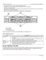
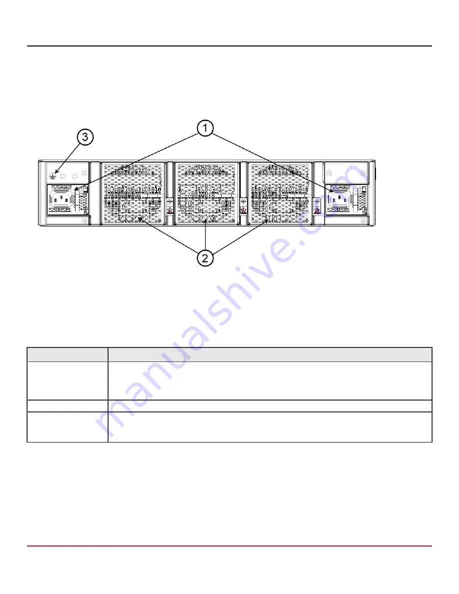
The chassis is grounded through a ground cable using the threaded ground lug connection on the nonport side of the
chassis. See item 3 in the following figure.
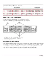
Figure 4: Nonport-Side View with AC Power Supply and Fan Assembly Units
1. Power Supplies
2. Fan Assemblies
3. Ground Cable Connector
After you have grounded the chassis, ensure that the following requirements are met.
Table 4: Facility Requirements
Type
Requirements
Electrical
•
An adequate supply circuit, line fusing, and wire size, as specified by the electrical rating on the switch
nameplate.
•
A circuit that is protected by a circuit breaker and grounded in accordance with local electrical codes.
See the
section for power supply specifications.
Thermal
•
Ambient air temperature not exceeding 40°C (104°F) while the switch is operating.
Rack (when rack-
mounted)
•
All equipment in the rack grounded through a reliable branch circuit connection.
•
The additional weight of the switch not to exceed the weight limits of the rack.
•
Rack secured to ensure stability if there is unexpected movement.
Quick Installation Checklist
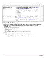
The following checklists provide a high-level overview of the basic installation process from the planning stage to the point
where the device comes online and is ready to be deployed. Completing all the tasks in the suggested order ensures
successful installation. Print these checklists and take them to the installation site.
G730-Install-IG100
15
Summary of Contents for Brocade G730
Page 94: ......


