G730-Install-IG100 Installation Guide
Brocade
®
G730 Switch Hardware Installation Guide
–
One 10/100/1000Mb/s RJ-45 Ethernet connector for the management connection. With EZSwitchSetup, this port
supports switch IP address discovery and configuration, eliminating the need to attach a serial cable to configure
the switch IP address.
–
One RS-232 3-wire (Tx, Rx, and GND) universal asynchronous receiver/transmitter (UART) serial port to the
baseboard management controller (BMC) with an RJ-45 connector for debugging the initial switch setup (if not
using EZSwitchSetup) and factory default restoration. Integral LEDs remain unlit always.
–
One external USB Type A connector.
License Options
The Brocade G730 Switch uses a capacity-based Ports on Demand (POD) license method. Refer to the
Brocade Fabric
OS Software Licensing Guide
for more details.
Port-Side View of the Device
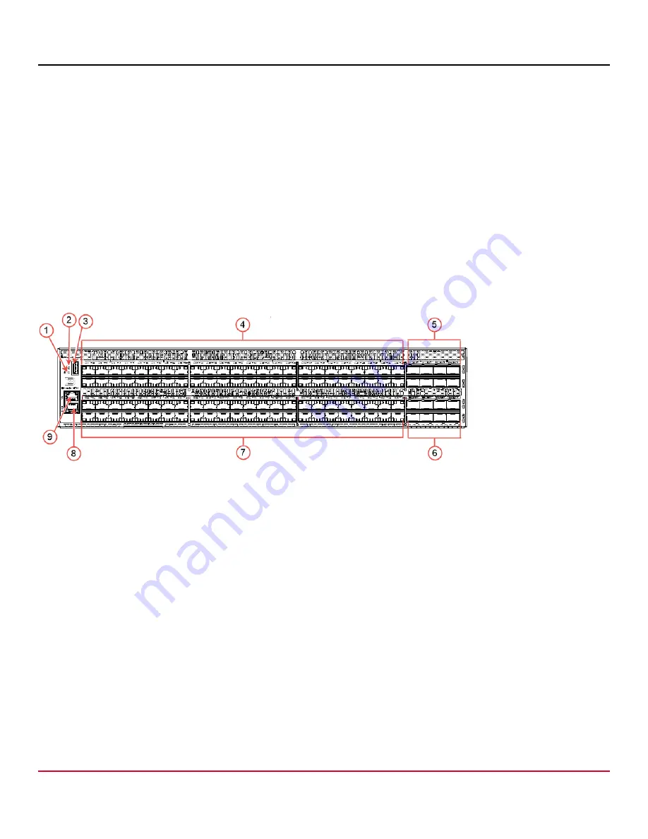
The following figure shows the port-side view of the Brocade G730 Fibre Channel Switch.
Figure 1: Port-Side View
1. System Power LED
2. System Status LED
3. USB Port
4. 48 SFP+ 64G FC Ports (FC Ports 0–47)
5. 8 DD 64G Ports (FC Ports 96–111)
6. 8 DD 64G Ports (FC Ports 112–127)
7. 48 SFP+ 64G FC Ports (FC Ports 48–95)
8. UART RJ-45 Serial Console Port
9. 10/100/1000Mb/s RJ-45 Ethernet Management Port
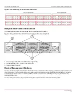
The following figure shows the port numbering for the Brocade G730 Switch. Trunk groups are outlined in red.
G730-Install-IG100
9
Summary of Contents for Brocade G730
Page 94: ......


