Broadcom
LPe3X00X-IG114-101
13
Emulex LPe31000-Series and LPe32000-Series Adapters
Quick Installation
Guide
2.6 Viewing the LEDs
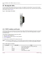
You can view the green and yellow LEDs through openings in the adapter's mounting bracket. The green LED indicates
firmware operation and the yellow LED indicates port activity or link speed. Each port has a corresponding set of green and
yellow LEDs as shown in
Figure 7
.
Figure 7: Optical Adapter LED Indicators
2.6.1 POST Conditions and Results
POST is the default mode of self-test for the LPe31000-series and the LPe32000-series adapters. No jumpers or connectors
are necessary for this test to run. These tests perform a quick confidence level check of the adapter before running the
operational software.
At a minimum, the following tests are performed by POST:
Flash boot image checksum test
Internal
ASIC
RAM
tests for proper
ECC
parity operation
NL_Port
loopback test
The following table summarizes POST conditions and results.
NOTE:
For the link rate conditions, there is a 1-second pause when the LED is off between each group of fast blinks (2,
3, 4, or 5). Observe the LED sequence for several seconds to be sure you have correctly identified the pattern.
Table 6: POST Conditions and Results
Green LED
Yellow LED
State
Off
Off
No SFP modules installed or boot failure (dead board)
Off
On
POST failure (dead board)
Off
Slow blink
Boot failure after POST
Off
Fast blink
Not defined
Off
Flashing
POST processing in progress
Summary of Contents for Emulex LPe31000
Page 26: ......


