background image

SR-IOV: Configuration and Use Case Examples

NetXtreme-E User’s Manual


February 26, 2018 • NetXtreme-E-UG100

Page 58

6.

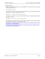
Enable Virtual Functions through Kernel parameters:

a. Once the driver is installed, lspci will display the NetXtreme-E NICs present in the system. Bus, device, 

and Function are needed for activating Virtual functions.

b. To activate Virtual functions, enter the command shown below:

echo X >/sys/bus/pci/device/0000\:Bus\:Dev.Function/sriov_numvfs

A typical example would be:

echo 4 > /sys/bus/pci/devices/0000\:04\:00.0/sriov_numvfs

7.

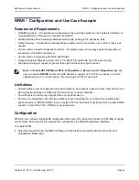
Check the PCI-E virtual functions:

a. The 

lspci

 command will display the virtual functions with DID set to 16D3 for BCM57402/BCM57404/

BCM57406, 16DC for non-RDMA BCM57412/BCM57414/BCM57416, and 16C1 or RDMA enabled 
BCM57412/BCM57414/BCM57416.

8.

Use the Virtual Manager to install a Virtualized Client system (VMs).

Refer to the Linux documentation for Virtual Manager installation. Ensure that the hypervisor’s built in driver 
is removed. An example would be 

NIC:d7:73:a7 rtl8139

. Remove this driver. 

9.

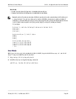
Assign a virtual function to the guest VMs.

a. Assign this adapter to a guest VM as a physical PCI Device. Refer to the Linux documentation for 

information on assigning virtual functions to a VM guest.

10.

Install 

bnxt_en

 drivers on VMs:

a. On the guest VMs, copy the 

netxtreme-bnxt_en-<version>.tar.gz

 source file and extract the 

tar.gz

 file. 

Change directory to each driver and run 

make; make install; modprobe bnxt_en

 (and 

bnxt_re

 if enabling 

RDMA). Make sure that the driver loads properly by checking the interface using modinfo command. The 
user may need to run 

modprobe -r bnxt_en

 to unload existing or inbox 

bnxt_en

 module prior to loading 

the latest built module.

11.

Test the guest VM connectivity to external world:

a. Assign proper IP address to the adapter and test the network connectivity.

Windows Case

1.

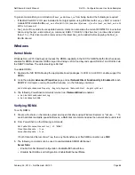
Enable SR-IOV in the NIC cards:

a. SR-IOV in the NIC card can be enabled using the HII menu. During the system boot, access the system 

BIOS -> Device Settings -> NetXtreme-E NIC -> Device Level Configuration

.

b. Set the Virtualization mode to SR-IOV.

Note: 

Use 

netxtreme-bnxt_en<version>.tar.gz

 to install both 

bnxt_re

 and 

bnxt_en

 for RDMA 

functionality on SRIOV VFs.

Note: 

Ensure that the PF interfaces are up. VFs are only created if PFs are up. X is the number of VFs 

that will be exported to the OS.

Summary of Contents for NetXreme-C

Page 1: ...NetXtreme E UG100 February 26 2018 User sManual NetXtreme E Broadcom NetXreme C and NetXtreme E USER S MANUAL...

Page 2: ...reserves the right to make changes without further notice to any products or data herein to improve reliability function or design Information furnished by Broadcom is believed to be accurate and reli...

Page 3: ...7416AXXXX 16 BCM957414M4140D 17 BCM957412M4120D 18 BCM957416M4160 19 Features 20 Software and Hardware Features 20 Virtualization Features 21 VXLAN 22 NVGRE GRE IP in IP Geneve 22 Stateless Offloads 2...

Page 4: ...lation 29 Supported Operating Systems 29 Installing Drivers 29 Windows 29 Dell DUP 29 GUI Install 29 Silent Install 29 INF Install 29 Linux 30 Module Install 30 Linux Ethtool Commands 31 VMware 32 Fir...

Page 5: ...SCSI Boot 49 Configuring the iSCSI Target 49 Configuring iSCSI Boot Parameters 50 MBA Boot Protocol Configuration 50 iSCSI Boot Configuration 51 Static iSCSI Boot Configuration 51 Dynamic iSCSI Boot C...

Page 6: ...itations 67 Known Issues 67 Windows 68 Kernel Mode 68 Verifying RDMA 68 User Mode 69 VMware ESX 70 Limitations 70 BNXT RoCE Driver Requirements 70 Installation 70 Configuring Paravirtualized RDMA Netw...

Page 7: ...Interface Card Regulatory Safety Table 1 Regulatory Approvals Item Applicable Standard Approval Certificate CE European Union EN 62368 1 2014 CB report and certificate UL USA IEC 62368 1 ed 2 CB repor...

Page 8: ...owing measures Reorient or relocate the receiving antenna Increase the separation between the equipment and receiver Consult the dealer or an experienced radio TV technician for help Table 3 Electroma...

Page 9: ...ceiver NDIS Name Broadcom NetXtreme E Series Dual port 10Gb SFP Ethernet PCIe Adapter UEFI Name Broadcom Dual 10Gb SFP Ethernet BCM57404A4041DLPC BCM57404A4041DC BCM957414A4141D BCM957414M4140D Speed...

Page 10: ...Functional Description NetXtreme E User s Manual February 26 2018 NetXtreme E UG100 Page 10 Figure 1 BCM957402A4020DC BCM957412A4120D Network Interface Card...

Page 11: ...Functional Description NetXtreme E User s Manual February 26 2018 NetXtreme E UG100 Page 11 Figure 2 BCM957404A4041DLPC BCM957414A4141D Network Interface Card...

Page 12: ...ional Description NetXtreme E User s Manual February 26 2018 NetXtreme E UG100 Page 12 Figure 3 BCM957406A4060DLPC BCM957416A4160D Network Interface Card Figure 4 BCM957414M4140D Network Daughter Card...

Page 13: ...Functional Description NetXtreme E User s Manual February 26 2018 NetXtreme E UG100 Page 13 Figure 5 BCM957412M4120D Network Daughter Card rNDC Figure 6 BCM957416M4160 Network Daughter Card rNDC...

Page 14: ...the cutout on the bracket as shown in Figure 7 The LED functionality is described in Table 6 Figure 7 BCM957402AXXXX BCM957412AXXXX Activity and Link LED Locations Table 6 BCM957402AXXXX BCM957412AXX...

Page 15: ...own in Figure 8 The LED functionality is described in Table 7 Figure 8 BCM957404AXXXX BCM957414AXXXX Activity and Link LED Locations Table 7 BCM957404AXXXX BCM957414AXXXX Activity and Link LED Locatio...

Page 16: ...Ds are visible through the cutout on the bracket as shown in Figure 9 The LED functionality is described in Table 8 Figure 9 BCM957406AXXXX BCM957416AXXXX Activity and Link LED Locations Table 8 BCM95...

Page 17: ...EDs are visible through the cutout on the bracket as shown in Figure 10 Figure 10 BCM957414M4140D Network Daughter Card rNDC Activity and Link LED Locations Table 9 BCM957414M4140D Network Daughter Ca...

Page 18: ...Network Daughter Card rNDC Activity and Link LED Locations Table 10 BCM957412M4120D Network Daughter Card rNDC Activity and Link LED Locations SFP Port 1 and 2 LED Type Color Behavior Notes Activity O...

Page 19: ...vities and link speed The LEDs are visible as shown in Figure 12 Figure 12 BCM957416M4160 Network Daughter Card rNDC Activity and Link LED Locations Table 12 BCM957416M4160 Network Daughter Card rNDC...

Page 20: ...per RSS queue 1 per NetQueue 1 per Virtual Machine Queue VMQ IP Checksum Offload Support for transmit and receive side TCP Checksum Offload Support for transmit and receive side UDP Checksum Offload...

Page 21: ...Pause Supported Auto negotiation Supported 802 1q VLAN Supported Interrupt Moderation Supported MAC VLAN filters Supported Table 14 Virtualization Features Feature Details Linux KVM Multiqueue Support...

Page 22: ...n the TPA context is identified by the 4 tuple Source IP destination IP source TCP port and destination TCP port TPA improves system performance by reducing interrupts for network traffic and lessenin...

Page 23: ...ues This packet classification combined with the ability to DMA packets directly into a virtual machine s memory allows the scaling of virtual machines across multiple processors Refer to the Windows...

Page 24: ...to 16 PFs per device Each partition is assigned its own configuration space BAR address and MAC address allowing it to operate independently Partitions support direct assignment to VMs VLANs etc just...

Page 25: ...Unsupported Combinations The combination of NPAR SR IOV RoCE and DPDK is not supported Table 15 NPAR SR IOV and RoCE SW Feature Notes NPAR Up to 8 PFs or 16 PFs SR IOV Up to 128 VFs total per chip Ro...

Page 26: ...sted in System Requirements 2 Verify that the server is using the latest BIOS 3 If the system is active shut it down 4 When the system shutdown is complete turn off the power and unplug the power cord...

Page 27: ...SFP SFP28 QSFP28 ports that support up to 100 Gbps These 100 Gbps ports can be divided into 4 x 25 Gbps SFP28 ports QSFP ports can be connected to SFP28 ports using 4 x 25G SFP28 breakout cables Supp...

Page 28: ...hing the system to a 10 Gbps Ethernet switch SFP28 The BCM957404AXXXX BCM957414XXXX and BCM957414AXXXX adapters have two SFP28 connectors used for attaching the system to a 100 Gbps Ethernet switch FT...

Page 29: ...executable format GUI Install When the file is executed a dialog box appears requesting user input The installer supports the driver only option Silent Install The executable can be silently executed...

Page 30: ...mand make make install modprobe r bnxt_en modprobe bnxt_en For RDMA functionality install both the bnxt_en and bnxt_re driver Use netxtreme bnxt_en version tar gz instead of bnxt_en version tar gz Mod...

Page 31: ...tx frames tx usecs irq tx frames irq ethtool x ethX Show RSS flow hash indirection table and RSS key ethtool s ethX autoneg on speed 10000 duplex full Enable Autoneg see Auto Negotiation Configuration...

Page 32: ...var run vmware vmkdevmgr pid This command is required after vmkload_mod bnxtnet for successful module bring up Table 20 VMware Commands Command Description esxcli software vib list grep bnx List the...

Page 33: ...g sections to use the Dell Update Package DUP Windows Broadcom NetXtreme E series controller firmware can be upgraded using the Dell DUP package The executable is provided in standard Windows x64 exec...

Page 34: ...umbo packet size Large Send offload V2 IPV4 Enable or Disable LSO for IPV4 Large Send offload V2 IPV6 Enable or Disable LSO for IPV6 Locally Administered Address User entered MAC address Override defa...

Page 35: ...Machine Queue Enable or Disable Default Enabled VLAN ID User configurable number Default 0 Table 22 Windows Event Log Messages Message ID Comment 0x0001 Failed Memory allocation 0x0002 Link Down Detec...

Page 36: ...illegal 0x001C Network controller configured for 25Gb full duplex link 0x0020 RDMA support initialization failed 0x0021 Device s RDMA firmware is incompatible with this driver 0x0022 Doorbell BAR siz...

Page 37: ...bonding 1 Execute the following command modprobe bonding mode balance alb This will create a bond interface 2 Add bond clients to the bond interface An example is shown below ifenslave bond0 ethX ife...

Page 38: ...ulti Boot Agent MBA UEFI iSCSI and Comprehensive Configuration Management CCM version numbers Device Level Configuration Main configuration page Device level configuration allows the user to enable SR...

Page 39: ...option to change the parameters through the Control S menu When Control S is pressed a device list will be populated with all the Broadcom network adapters found in the system Select the desired NIC...

Page 40: ...41 Note In NPAR NIC partitioning devices where one port is shared by multiple PCI functions the port speed is preconfigured and cannot be changed by the driver Note Regarding link speed AN when using...

Page 41: ...25G Not supported P1 AN 10G P1 AN 10G Not supported P1 AN 25G P1 AN 10G P1 AN 10G P1 AN 10G P2 no AN P2 no AN P2 AN 1G P2 AN 10G P2 AN 1G P2 AN 1G P2 AN 10G P2 AN 1 10G AN Enabled 25G P1 AN 25G Not su...

Page 42: ...link No link No link No link No link No link No link No link Forced 10G No link 10G No link No link No link No link No link No link No link No link Forced 25G No link No link 25G No link No link No l...

Page 43: ...ion is set to IEEE 802 3by and falls back to 25G 50G consortiums Link speed and Flow Control Pause must be configured in the driver in the host OS Windows Driver Settings To access the Windows driver...

Page 44: ...D full n iface This command sets the forced speed to 10 Gbps esxcli network nic set a n iface This enables linkspeed auto negotiation on interface iface esxcli network nic pauseParams list Use this co...

Page 45: ...Table 26 shows all supported configurations with a link partner For the NetXtreme E Ethernet controller the FEC supports Base R FEC CL74 and RS FEC CL91 CL108 Table 27 shows all supported configuratio...

Page 46: ...CM5741X Ethernet controllers Table 27 Supported FEC Configurations for the BCM5741X Local FEC Setting Link Partner FEC Setting Force Speed No FEC Force Speed Base R FEC CL74 Force Speed RS FEC CL91 CL...

Page 47: ...upported when auto negotiating at 25G or 10GbE This means that if one side is auto negotiating and the other side is not the link will not come up Figure 13 State Machine for the Media Auto Detect Fea...

Page 48: ...R AN Disabled Link Link Auto FEC Link Link with Base R Base R Link with Base R Link with Base R Table 30 Media Auto Detect for the BCM5741X Link Partner Link Training Setting Link Partner Settings Me...

Page 49: ...e target vendor For information on configuring the iSCSI target refer to the documentation provided by the vendor The general steps include 1 Create an iSCSI target 2 Create a virtual disk 3 Map the v...

Page 50: ...ion is entered through the iSCSI Initiator Parameters Configuration screen CHAP Authentication Controls whether the iSCSI boot host software uses CHAP authentication when connecting to the iSCSI targe...

Page 51: ...the General Parameters menu set the following TCP IP parameters via DHCP Disabled For IPv4 IP Autoconfiguration Disabled For IPv6 non offload iSCSI parameters via DHCP Disabled CHAP Authentication Dis...

Page 52: ...options see Table 31 on page 50 If DHCP Option 17 is used the target information is provided by the DHCP server and the initiator iSCSI name is retrieved from the value programmed from the Initiator P...

Page 53: ...AP Authentication Ensure that CHAP authentication is enabled on the target To enable CHAP authentication 1 From the General Parameters screen set CHAP Authentication to Enabled 2 From the Initiator Pa...

Page 54: ...the iSCSI client than DHCP option 17 In this configuration three additional suboptions are provided that assign the initiator IQN to the iSCSI boot client along with two iSCSI target IQNs that can be...

Page 55: ...ISAN as shown in General Parameters of the iSCSI Boot Configuration menu The content of Option 16 should be 2 byte length DHCP Vendor ID DHCPv6 Option 17 Vendor Specific Information DHCPv6 Option 17 v...

Page 56: ...D 10 is created with multicast group 239 0 0 10 and is associated with physical network port pxp1 on each server An IP address for the host is created on each server and associated that to VXLAN inter...

Page 57: ...ibvirt and Qemu 4 Enable the iommu kernel parameter a The IOMMU kernel parameter is enabled by editing etc default grub cfg and running grub2 mkconfig o boot grub2 grub cfg for legacy mode For UEFI mo...

Page 58: ...the guest VMs a Assign this adapter to a guest VM as a physical PCI Device Refer to the Linux documentation for information on assigning virtual functions to a VM guest 10 Install bnxt_en drivers on...

Page 59: ...per V Manager create your Virtual Switch with the selected NetXtreme E interface 8 Check the Enable Single Root I O Virtualization SR IOV box while creating the Hyper V Virtual Adapter 9 Create a Virt...

Page 60: ...ty to set view the miscellaneous driver parameters that are not natively supported in esxcli such as link speed to 25G show driver firmware chip information show NIC configuration NPAR SRIOV For more...

Page 61: ...n PF1 esxcfg module s max_vfs 4 bnxtnet reboot required To enable VFs on a set of PFs use the command format shown below For example to enable four VFs on PF 0 and 2 VFs on PF 2 esxcfg module s max_vf...

Page 62: ...ettings must be suppressed to avoid contention For example Speed Duplex Flow Control and similar physical settings are hidden by the device driver to avoid contention Non ARI systems enable only eight...

Page 63: ...uration Menu option is available from the main NIC Configuration Menu associated with each physical port 3 The NIC Partition Configuration Menu shown below allows the user to choose the number of part...

Page 64: ...dwidth between all partitions Value 0 100 BW Limit Maximum percentage of available bandwidth this partition is allowed Value 0 100 BW Reservation Valid Functions as an on off switch for the BW Reserva...

Page 65: ...rticipate in processing receive packets from that NIC Per processor CPU utilization should be monitored to ensure that there are no hot processors after this change Reduce memory allocation by reducin...

Page 66: ...ich is part of released gzip compressed tar archive bnxt_re RoCE driver libbnxtre User mode RoCE library module BNXT_RE Driver Dependencies The Bnxt_re driver requires a special RoCE enabled version o...

Page 67: ...stall the NetXtreme E Linux RoCE User Library a tar xzf libbnxtre 0 0 18 tar gz b cd libbnxtre 0 0 18 c configure make make install d cp bnxtre driver etc libibverbs d e echo usr local lib etc ld so c...

Page 68: ...e The default setting is RoCEv1 To enable RDMA 1 Upgrade the NIC NVRAM using the appropriate board packages In CCM or in UEFI HII enable support for RDMA 2 Go to the adapter Advanced Properties page a...

Page 69: ...l32 exe bxndspi dll Config install more Note By default the driver sets up two RDMA connections for each network share per IP address on a unique subnet The user can scale up the number of RDMA connec...

Page 70: ...he following command esxcfg module s disable_roce 0 bnxtnet Please use the ESX6 5 L2 driver version 20 6 9 0 RoCE supported L2 driver or above Installation To install the RoCE driver 1 Copy the bnxtro...

Page 71: ...In the Settings page expand System and click Advanced System Settings to show the Advanced System Settings key pair value and its summary 3 Click Edit to bring up the Edit Advanced System Settings Fi...

Page 72: ...conf by running ldconfig 6 Load ib modules using modprobe rdma_ucm 7 Load the PVRDMA kernel module using insmod pvrdma ko 8 Assign an IP address to the PVRDMA interface 9 Verify whether the IB device...

Page 73: ...this user manual The following settings in the UEFI HII menu are required to enable DCBX support System Setup Device Settings NetXtreme E NIC Device Level Configuration QoS Profile Default QoS Queue...

Page 74: ...er bridging DCBX Willing Bit The DCBX willing bit is specified in the DCB specification If the Willing bit on a device is true the device is willing to accept configurations from a remote device throu...

Page 75: ...Name SMB class PS C Get NetQosTrafficClass Name Algorithm Bandwidth Priority Default ETS 100 0 7 Use the following to create Traffic Class Strict Priority C New NetQosTrafficClass name SMB class prior...

Page 76: ...SrcPrefixMatchCondition 10 235 2 0 24 IPProtocolMatchCondition both PriorityValue802 1Action 7 PS C Get NetQosPolicy name network management Name Network Management Owner 382ACFD 1E73 46BD A0A0 4EE0E5...

Page 77: ...the port speed of each port must be compatible with the port speed of the other port 10 Gbps and 25 Gbps are not compatible speed If one port is set to 10 Gbps the other port can not be set to 25 Gbp...

Reviews: