Broadcom
P411W-32P-UG104
8
P411W-32P PCIe 4.0
User Guide
NVMe Switch Adapter
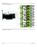
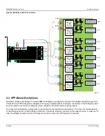
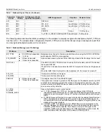
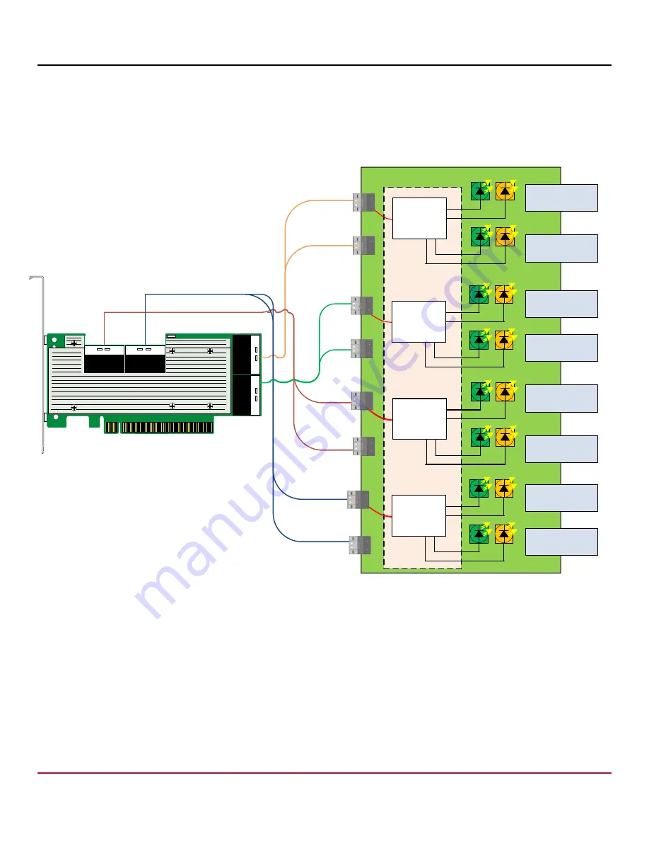
The following figure shows expected connections to a backplane that uses x4 SFF-8654 connectors from the adapter to
NVMe drives by using VPP over I
2
C for backplane management. The red line indicates the I2C bus connection. For proper
LED functionality when using Broadcom supplied cables, connect the P0 labeled leg of the cable to the PCA9555 target.
Refer to the backplane's documentation to verify which host facing connector maps to a given slot.
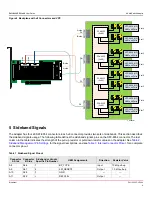
Figure 3 Backplane with x4 Connectors and VPP
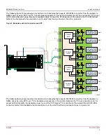
The following figure shows expected connections to a backplane that uses x8 SFF-8654 connectors from the adapter to
NVMe drives by using VPP over I
2
C for backplane management. The red line indicates the I
2
C bus connection, and, for
proper LED functionality, the backplane must connect the VPP target’s I
2
C connection to the A side of the x8 SFF-8654
connector. Refer to the backplane's documentation to verify which host facing connector maps to a given slot.
?
#
#
#
#
3&&5
.6-EX$RIVE
3&&5
.6-EX$RIVE
3&&5
.6-EX$RIVE
3&&5
.6-EX$RIVE
0
0
0
0
3LOT
3LOT
3LOT
3LOT
3&&5
.6-EX$RIVE
3&&5
.6-EX$RIVE
3&&5
.6-EX$RIVE
3&&5
.6-EX$RIVE
3LOT
3LOT
3LOT
3LOT
0
0
0
0
0#!
X
0#!
X
0#!
X
0#!
X
Summary of Contents for P411W-32P
Page 20: ......


