background image

2

CONTENTS

Safety Precautions ................................................................... 2

Model and Serial No. Identification ....................................... 2

Transporting Compactor ......................................................... 2

Manually Raising and Lowering Ram .................................... 2

Troubleshooting Guide .................................................... 3 & 4

Component Replacement ............................................. 5, 6 & 7

Greasing Compactor Mechanism ............................................ 7

Wiring Diagrams ...................................................................... 8

Parts Lists .................................................................... 9 thru 12

SAFETY PRECAUTIONS

ALWAYS UNPLUG COMPACTOR FROM WALL OUTLET

BEFORE SERVICING.

The service information is intended for use by a service techni-

cian who is familiar with proper and safe procedures to be fol-

lowed when repairing electrical appliances and who is equipped

with proper tools and testing devices. Repairs attempted or made

improperly can result in personal injury or property damage.

Hazards may develop from improper assembly or adjustments.

While making repairs, persons not having the proper background

may subject themselves to the risk of injury or electrical shock

which can be serious or even fatal.

IMPORTANT - NOTE TO THE CONSUMER

If you perform service on your own Broan products, you must

assume responsibility for personal injury or property damage

which may result.

MODEL AND SERIAL NO. IDENTIFICATION

The specification label with model and serial numbers is locat-

ed on the inside of the cabinet. It is visible after opening the

drawer.

TRANSPORTING COMPACTOR

When transporting compactor, the ram should be electrically or

manually extended down into the drawer, preferably against a

load of stacked newspapers or other suitable material. If this is

not done, damage to the trunnion nut may occur.
Never transport compactor on its back or front. Damage to the

gearbox may occur. If it cannot be transported upright, it is

preferable to place it on its side.

MANUAL RAISING AND LOWERING OF RAM

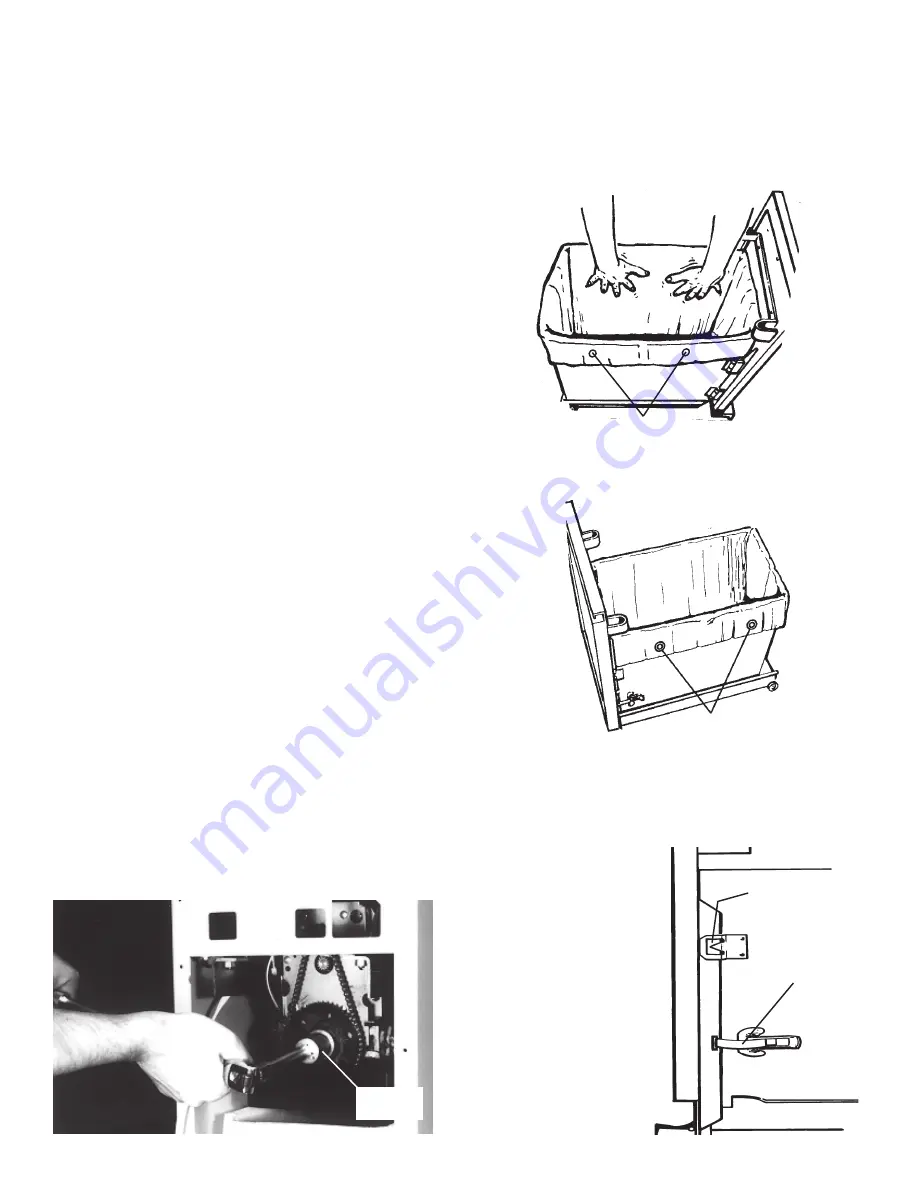
Unplug compactor cord from wall socket. Remove back panel.

The ram may be raised or lowered manually by using a 15/16"

socket to turn the drive screw nut. Clockwise will lower ram,

counterclockwise will raise it.

BAG INSTALLATION

DO NOT use plastic bags other than those which have been

designed for use in this compactor. Unauthorized bags may be-

come caught in the mechanism.
With the drawer extended to the second stop, release the con-

tainer latch and swing open door. Slide bag into drawer from

front to back. Fold bag over top rim of drawer on all sides.

Press bag into all corners of the drawer. Smooth and shape the

bag carefully - this will prevent the bag from being torn by the

ram during compaction.

Using buttons on side of drawer, button bag in place by using

prepunched holes in side of bag. NOTE: If you have difficulty

installing bag, move drawer completely from unit by lifting

front of drawer slightly and pulling forward (place on rug or

other surface to protect

floor). This will clear back

of container from housing

for easier bag installation.

Swing door shut and latch

it. Bag is locked between

door flange and drawer.

When door is closed and

latched properly, door

guide “V” will be snug in

“V” groove in drawer

flange. Bag should be

captured in “V” guide.

Failure to align “V” prop-

erly or to latch drawer to

door will cause the com-

pactor to function im-

properly.

2

15/16”

SOCKET

PREPUNCHED HOLES

DRAWER BUTTONS

“V” GROOVE

CONTAINER

LATCH

Summary of Contents for 1050L-C

Page 1: ...Broan NuTone LLC 926 West State Street Hartford WI 53027 1 800 637 1453 5 00 MODELS 1050L C 1051L C MODELS 1055 K 1059 C TRASH COMPACTOR SERVICE MANUAL ...

Page 2: ... trunnion nut may occur Never transport compactor on its back or front Damage to the gearbox may occur If it cannot be transported upright it is preferable to place it on its side MANUALRAISINGANDLOWERINGOFRAM Unplug compactor cord from wall socket Remove back panel The ram may be raised or lowered manually by using a 15 16 socket to turn the drive screw nut Clockwise will lower ram counterclockwi...

Page 3: ...est motor replace if necessary III Will not run hums when key held in start position Defective upper limit switch Loose connection Defective motor Plastic bag caught in trunnion nut Replace Repair Test motor replace if necessary Remove plastic bag See section on motor replacement for test procedure See section on removing bags from tunnion nut Do not use bags other than the compactor trash bag des...

Page 4: ...es It is not necessary to replace motor Roller tracks should be kept clean to keep glass particles from wearing out rollers Apply Locktite to threads Ram does not travel to bottom of drawer Ex tends to 6 from bottom of basket As more trash is deposited and unit is operated compaction will take place Bottles and cans should be placed randomly in center of drawer Cans and bottles neatly arranged are...

Page 5: ...move key switch control bracket assembly Remove back panel 5 Place box in cabinet and lower ram manually by turning 15 16 nut on sprocket clockwise Box should support weight of power pack 6 Remove the four 5 16 nuts supporting the power pack in the cabinet 7 Disconnect ground wire attached to cabinet 8 Turn 15 16 nut counterclockwise causing power pack to lower down out of cabinet Pull power pack ...

Page 6: ...revolutions to spin off nut TRUN NION must be reinstalled to same position 5 Reinstall trunnion nut and retainer CONTINUAL STRIPPING OF TRUNNION NUT POSSIBLE CAUSES 1 Incorrect assembly of trunnion assembly 2 Transporting compactor incorrectly 3 Burr on main drive screw sharp edge on lead in thread 4 Upper limit switch adjustment REMOVING PLASTIC BAGS FROM TRUNNION NUT Only the trash compactor bag...

Page 7: ...mounting plate If the mount ing screws are loose gearbox movementmaybethecause If the gearbox mounting plate is bent where it meets the motor trunnion eitherstraightenorre place the gearbox Somechainloosenessisnormal and may increase as the com pactorisused Seldomdoesthe chain stretch to the point where it is too loose GEARBOX 1 Lower ram manually until there is approximately 11 to 12 between the ...

Page 8: ...tive Check the continuity of the motor CHECK CONTINUITY Black to Orange If open replace motor Red to Orange If open replace motor Gray to Orange If open replace motor Green to Motor Frame If open inspect wire to be sure it is properly attached to motor frame 1 Lower ram manually until there is approximately 7 between the bottom assembly and the ram 2 Disconnect molex connector from motor to wire h...

Page 9: ...3110936 Key Knob Type Model 1050L 1055 93110935 Key Knob Type Model 1051L 1059 17 91009865 Cabinet Includes Mounting Stud Strips 91007999 Models 1050L 1051L 18 91006357 Bottom Assembly Includes Rollers 93470012 19 93470012 Rollers 21 91011979 Latch Box Assembly 22 OPTIONAL Cutting Board order Model 1004 23 92007052 Storage Compartment Models 1050L 1051L only 24 93260447 Nut Whizlock 5 16 18 25 934...

Page 10: ...3260443 Push On Retainer 77 93420442 Pin Upper Rear 78 93710029 Spacer Rail Rear 80 93380632 Shaft Lower 7 218 Long 82 92004582 Link Main 2 Hole 83 91005183 Link Assembly Peened 84 92004584 Ram Mounting Channel 85 91009243 Ram Platen 86 93170265 Cap Screw Hex 5 16 18 x 87 93710026 Spacer Ram Front 88 93710030 Spacer Ram Rear 89 93160408 Screw 10 32 x 625 SC HEX HD 93770071 Wire Harness MODELS 1050...

Page 11: ... Reverse Thrust Bearing 114 93180002 Cap Screw Socket HD 10 32 x 1 2 115 93250907 Washer 81 I D 116 93380619 Main Drive Screw 119 93250913 Washer Thrust 120 93110458 Trunnion Bearing 121 93300442 Motor Trunnion 122 93260457 Nut Hex 10 32 123 93150487 Screw 10 124 91011704 Sheet Metal Trunnion 125 93840003 Trunnion Nut 126 92008438 Trunnion Nut Retainer 127 93420558 Screw Guard Guide 128 93110972 S...

Page 12: ...d 138 93360100 Knob Latch Lever Model 1050L 1055 93360141 Knob Latch Lever Model 1051L 1059 139 93370334 Handle 140 92007833 Door 142 93110514 Toe Space Cover Model 1050L 1051L 1055 92008715 Toe Space Cover Model 1059 143 93650007 Side Door Trim 144 99230342 Rivet Pop SD 41 BS 1 8 145 93650008 Bottom Door Trim 146 93100511 Rubber Door Activator 151 93650057 Door Panel Black Biscuit OPTIONAL 910099...

Reviews: