background image

Page 5

MODELS   350 • 350BK • 350BR • 355 • 355BK • 355BR

356 • 356BK • 356BR • 358

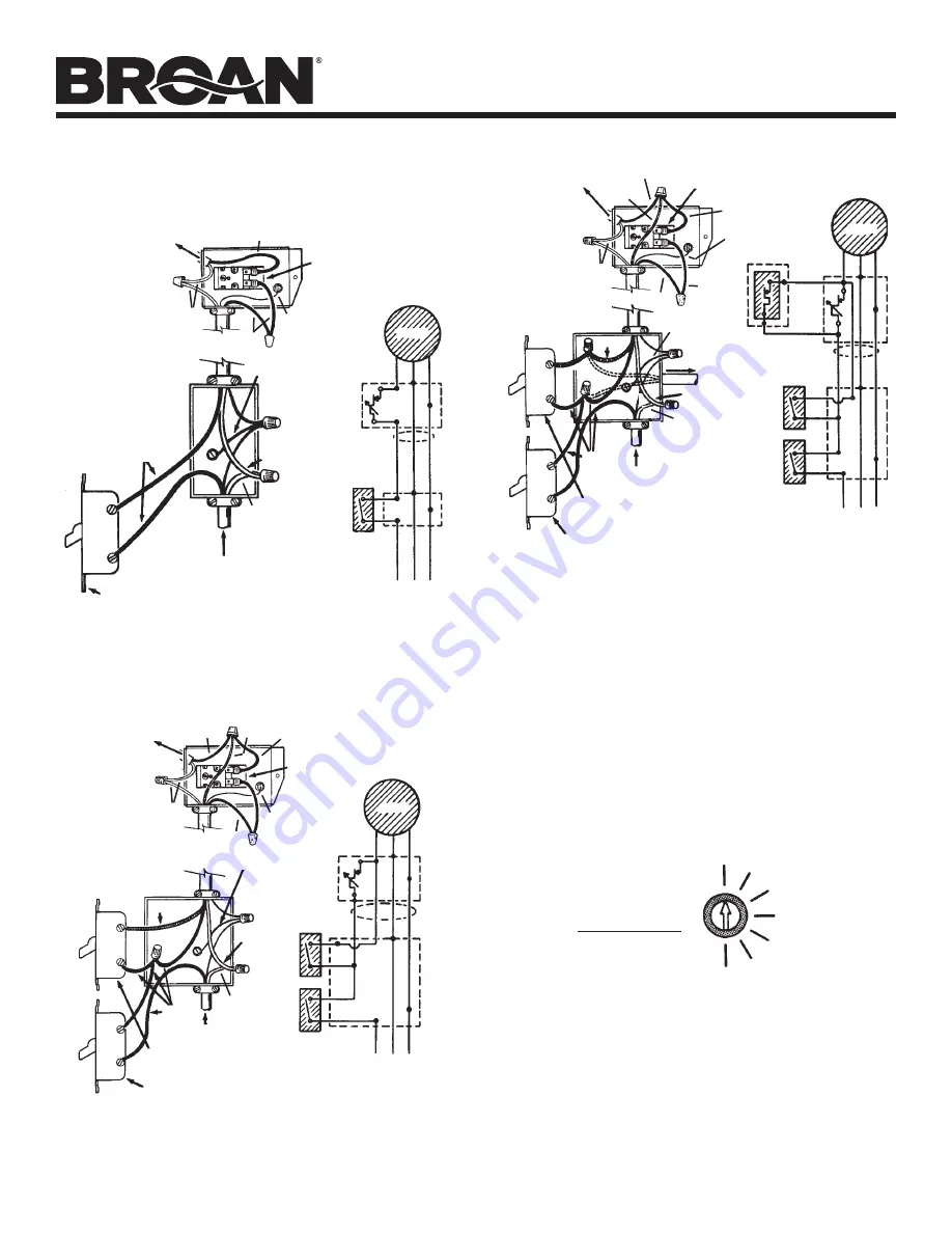
2.  For standard installation, connect the two leads in the ther-

mostat wiring box to the two power leads. Attach ground wire 
from the power cable to the green screw in the box.

TO

MOTOR

GROUND TO

SWITCH

BOX

WHITE

BLACK

THERMOSTAT

WHITE

MASTER
ON-OFF SWITCH

120 VOLTS

LINE IN

MOTOR

VENTILATOR
WIRING BOX

MASTER

ON-OFF
SWITCH

BLK

GRD

WHT

This diagram shows how to by-pass the thermostat to turn the 
ventilator on or off manually.

BLACK

BLK

GRD

WHT

TO

MOTOR

BLACK

THERMOSTAT

WHITE

RED

GROUND TO

SWITCH

BOX

WHITE

120 VOLTS

LINE IN

BLACK

RED

THERMOSTAT BY-PASS SWITCH
(SHOULD NORMALLY BE IN “OFF” POSITION)

MASTER
ON-OFF SWITCH

MOTOR

VENTILATOR
WIRING BOX

MASTER

ON-OFF
SWITCH

BLK

GRD

WHT

BLK

GRD

WHT

THERMOSTAT

BY-PASS
SWITCH

RED

TO

MOTOR

BLACK

THERMOSTAT

WHITE

RED

WHITE

120 VOLTS

LINE IN

RED

THERMOSTAT BY-PASS SWITCH
(SHOULD NORMALLY BE IN “OFF” POSITION)

MASTER
ON-OFF SWITCH

MOTOR

VENTILATOR
WIRING BOX

MASTER

ON-OFF
SWITCH

BLK

GRD

WHT

BLK

GRD

WHT

THERMOSTAT

BY-PASS
SWITCH

RED

BLACK

This diagram shows how to wire a humidistat.

3.  Replace the metal cover plate over the thermostat wiring box 

and fasten securely.

4.  The thermostat setting determines the temperature at which 

the ventilator turns “on”. The ventilator automatically turns off 
when the attic temperature is 10

O

F lower than the thermostat.

If you want the ventilator to operate at a different temperature, 
insert a screwdriver into the slot and turn the indicator to the 
desired temperature.
The ventilator will now turn “ON” at this temperature and “OFF” 
10

O

F lower.

70

O

F

80

O

F

90

O

F

100

O

F

110

O

F

120

O

F

130

O

F

FAN ON

TEMPERATURE

Indicator shown rotated fully counterclockwise for a setting 
of 70

O

F.

HUMIDISTAT

TO

HUMIDISTAT

BLACK

GROUND TO

SWITCH BOX

WHITE

BLACK

BLACK

GROUND TO

SWITCH BOX

WHITE

BLACK

BLACK

BLACK

GROUND TO

SWITCH BOX

WHITE

GROUND TO

SWITCH BOX

1.  Remove the thermostat wiring box cover plate. Bring the power 

cable at least 6" into the ventilator wiring box. Fasten power 
cable to box with appropriate connector.

Summary of Contents for 350

Page 1: ... in locations readily accessible to people or animals 4 Fan is equipped with a thermostat which may start fan automati cally To reduce risk of injury or electric shock while servicing or cleaning unit switch power off at service panel and lock service panel to prevent power from being switched on accidentally When the service disconnecting means cannot be locked securely fasten a prominent warning...

Page 2: ...entilator top is level with the roof peak it can t be seen from the street Keep this approximate location in mind as you work from within the attic 2 Mark a spot halfway between rafters 3 Drill a guide hole through the roof at this mark 4 Cut out the template found on the carton 5 Push a large nail through the center of the cardboard template and into the guide hole Usingthelargehalfofthetemplate ...

Page 3: ...ate 8 Drill a large starting hole for the sabre saw just inside of the line 9 Cut out the roof board s inside of the line 10 For proper removal of roofing nails draw a 22 square centeredaroundthehole Removenailsholdingshingles down from top two thirds of square 11 Slide the flashing under the shingles Start two thirds of the way down from the top of the 22 square Do not bend the shingles any more ...

Page 4: ...356BR 358 Page 4 12 Carefully lift shingles and nail flashing securely to the roof using galvanized roofing nails 13 Using a good grade of roofing cement material seal all of the shingles and heads of nails DO NOT seal the bottom edge of the flashing ...

Page 5: ...N OFF SWITCH MOTOR VENTILATOR WIRING BOX MASTER ON OFF SWITCH BLK GRD WHT BLK GRD WHT THERMOSTAT BY PASS SWITCH RED BLACK This diagram shows how to wire a humidistat 3 Replace the metal cover plate over the thermostat wiring box and fasten securely 4 The thermostat setting determines the temperature at which the ventilator turns on The ventilator automatically turns off when the attic temperature ...

Page 6: ...1 2 3 Required 10 99170245 8B 18 x 3 8 Sheet Metal Screw 3 Required 11 98009756 Wiring Box Models 350 350BK 350BR 355 355BK 355BR 358 98009886 Wiring Box Models 356 356BK 356BR 12 99150471 Green Ground Screw 10 32 x 1 2 Hex Washer Head 13 99030144 Adjustable Thermostat 14 97005329 Lead Wire Assembly 15 16 990717160 Wiring Box Cover with Label Model 350 990717161 Wiring Box Cover with Label Model 3...

Page 7: ...Page 7 MODELS 350 350BK 350BR 355 355BK 355BR 356 356BK 356BR 358 SERVICE PARTS Replacement parts can now be ordered on our website Please visit us at www Broan com ...

Page 8: ...f any implied warranty is limited to the one year period as specified for the express warranty Some states do not allow limitation on how long an implied warranty lasts so the above limitation may not apply to you BROAN NUTONE S OBLIGATION TO REPAIR OR REPLACE AT BROAN NUTONE S OPTION SHALL BE THE PURCHASER S SOLE AND EXCLUSIVE REMEDY UNDER THIS WARRANTY BROAN NUTONE SHALL NOT BE LIABLE FOR INCIDE...

Reviews: