Page 3
MODELS 744L • 744RL • 744RNL
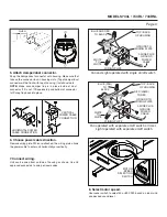
HORIZONTAL POWER
CABLE CONNECTION
VERTICAL
POWER CABLE
CONNECTION
WIRING PLATE
WHITE
TO
WHITE
BLUE (FAN)
TO
BLACK
TOP / BACK
OF HOUSING
3-WIRE PLUS
GROUND
POWER
CABLE
GROUND TO
WIRING PLATE
Fan operated with separate on/off switch or timer.
Light operated with separate on/off switch.
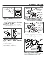
6. Choose power cable direction.
Remove wiring plate. When re-attached, the wiring plate allows
the power cable to enter unit horizontally or vertically.
7. Connect wiring.
Unit can be wired from outside of housing as shown. Use UL
approved connectors to wire per local codes.
Fan and Light operated with single on/off switch
RED (LAMP)
TO RED
WIRING PLATE
WHITE
TO
WHITE
BLUE AND RED
TO BLACK
TOP / BACK
OF HOUSING
2-WIRE PLUS
GROUND
POWER
CABLE
GROUND TO
WIRING PLATE
FLUSH
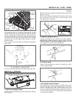
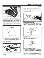
5. Attach damper/duct connector.
Snap the damper/duct connector onto housing. Make sure that
tabs on the connector lock in housing slots. (Top of damper/duct
connector will be flush with top of housing.) Install ductwork.
NOTE:
Make sure damper flap is in place inside of duct
connector. If it is not:
Squeeze top and bottom of connector
to
snap flap back into place.
80 C
FM 5
0
80 C
FM 5
0
8. Select motor speed.
Use rocker switch to select 50 or 80 CFM, based on room size
and desired sound level.
MOTOR
SPEED
SELECTION
SWITCH


