
Page 4
MODELS 744L • 744RL • 744RNL
1100709D
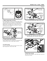
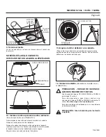
11. Attach trim ring / baffle to housing.
Use a pencil to insert one end of each spring into the holes on the
lamp bracket. Center trim ring / baffle in ceiling opening.
12. Install bulb.
(Bulb not included with Model 744L.)
FINISHED
CEILING
MATERIAL
HOUSING
COLLAR
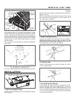
9. Finish ceiling.
Cut an opening in finished ceiling material for housing collar.
SPRINGS
TRIM RING / BAFFLE
LAMP
BRACKET
CAUTION: Disconnect power at service entrance
before cleaning, servicing, or selecting motor
speed.
CAUTION - RISK OF FIRE: 75W MAX. LAMP
Use R30, BR30, PAR30L, or PAR30LN lamps only (75W
Max.).
For wet locations (tub or shower) - use PAR30L or
PAR30LN (75W Max.) lamp only.
Use no other lamp
types.
Do not install a lamp indentified for use only in enclosed
luminaries.
!
CLEARANCE
HOLE
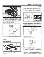
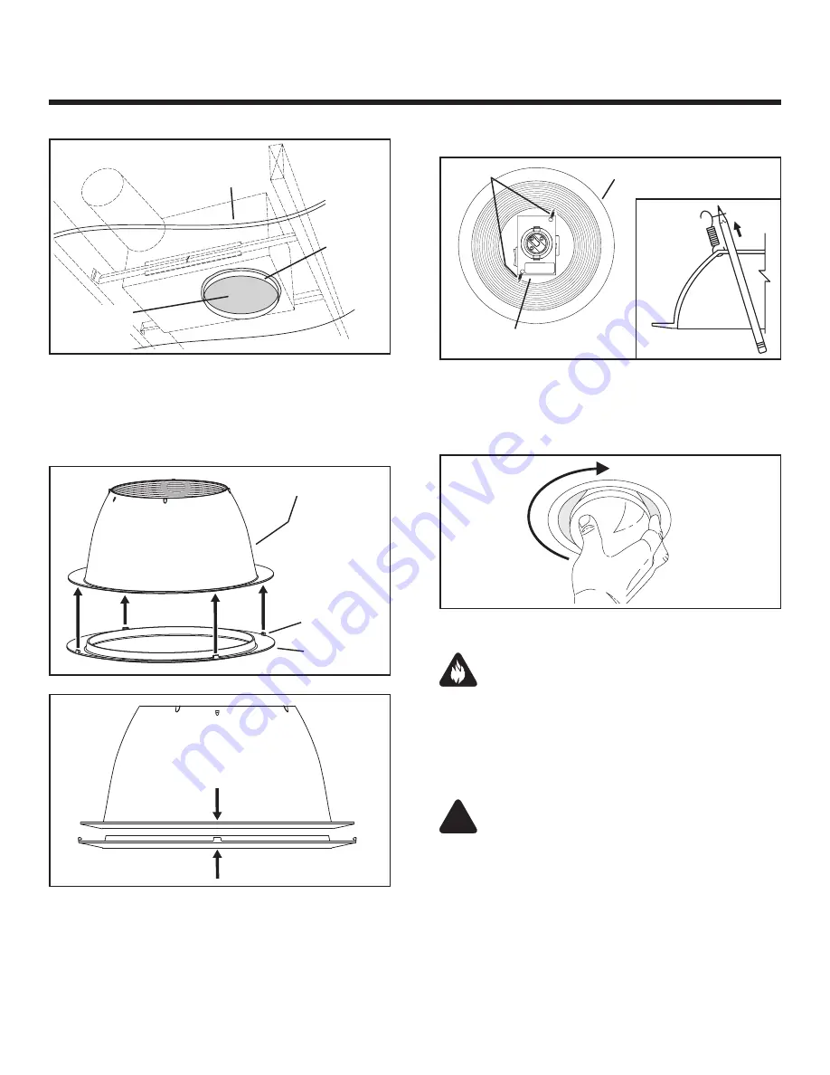
10. Install optional trim ring to trim ring / baffle.
(Trim rings not included with Model 744L.)
Remove the cardboard protector from inside the housing collar.
Place trim ring over trim ring / baffle.
Place fingers directly above and below tab (as shown with arrows
and squeeze to snap tab securely to trim ring / baffle.
Repeat for each of the 4 tab locations.
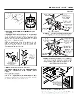
SPRINGS
TRIM RING / BAFFLE
LAMP
BRACKET
Securely attach optional trim ring.
TRIM RING / BAFFLE
TABS (4)
TRIM RING
Place trim ring
over trim ring / baffle.
Reverse Step 1 to
re-install trim ring / baffle
into housing.
DEV-10141
Use a pencil to unhook
springs and remove
trim ring / baffle
from housing.
1
2
Place fingers directly
above and below tab
(as shown with arrows).
Squeeze to snap tab
securely to
trim ring / baffle.
Repeat for each of the
4 tab locations.
3
4
DO NOT INSTALL TRIM RING WHEN
BAFFLE IS ALREADY ATTACHED TO FAN.