14
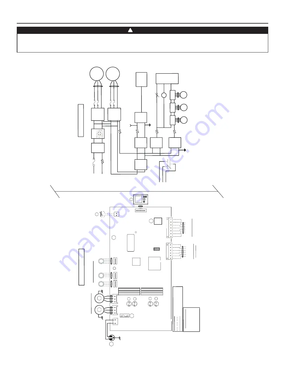
4. WIRING DIAGRAM
BLK
BLK
GR
N
LO
G
IC
D
IA
G
R
A
M
W
IR
IN
G
C
OL
O
R
C
OD
E
B
LK
B
LA
C
K
B
LU
B
LU
E
GR
N
G
R
E
E
N
R
E
D
R
E
D
W
H
T
W
HIT
E
Li
ne
v
olt
ag
e
fa
ct
or
y
w
iri
ng
Lo
w
v
ol
tag
e
fa
ct
ory
w
irin
g
Low
v
ol
tag
e
fie
ld
wi
rin
g
(E
xh
au
st
)
BLU
RE
D
120VAC
60
H
z
W1
GRN
F
1
1
P
ow
er
LE
D
J1
M2
D
amp
er
Step
pe
r
M
ot
or
s
Y
M1
W
H
T
B
LK
A
1
M
A
IN
E
LE
C
T
R
O
N
IC
A
S
S
E
M
B
LY
M1
Po
w
er
S
up
pl
y
(1
5V
D
C)
Li
ne
N
eu
tra
l
K1
G
Gf
AC
Li
ne
Filte
r
J1-2
F
1
H
igh
V
ol
tag
e
(120VAC
)
J1-1
To
J2
M
C
U
K1
M
3
S
tepp
er
D
river
T
o
J5
WIR
IN
G
D
IA
G
R
A
M
BD
M
1
5A
/1
25
V
A
C
J2
J3
J5
J6
J7
1
1
1
1
1
J7
a
J15
a
1
A2
LC
D
A
S
S
E
M
B
LY
GR
N
Ve
nt
ila
tio
n
F
an
M
ot
or
s
BLU
RE
D
M2
M3
M
4
(S
up
pl
y
)
(S
up
pl
y
)
*
O
pt
io
na
l
(R
ec
irc
)
(E
xh
au
st
)
MC
U
S
er
ial
N
um
be
r
Is
ol
at
io
n
T
ra
ns
fo
rm
er
M
ot
or
F
us
es
F2
F3
F
4
F
5
V
W
Gf
C
G
R
*
O
pt
io
nal Ce
ntral
F
orced-
A
ir
S
yste
m
W
irin
g
(Is
ol
at
ed
24VA
C
)
OVR
LED
12V
D-
D+
GND
M
ai
n
an
d
A
ux
ill
ia
ry
C
on
tr
ol
s
W
iri
ng
Ther
m
ist
or
R
1
R
T1
(N
T
C)
B
rid
ge
IP
M
M
ot
or
1
IP
M
M
ot
or
1
F
3
F
2
M2
To
J3
F
5
F
4
C
en
tr
al
F
or
ce
d-
A
ir
S
ys
te
m
R
el
ay
K1
PT
C3
Is
olat
ed
S
up
pl
y
(12VDC
)
Isolat
ed
S
uppl
y
(3
.3
VD
C)
J9
J1
3
Lo
gic
S
up
pl
y
(3
.3
V
DC
)
P
T
C2
T
o
J9
Lo
gic
S
up
pl
y
(1
2VD
C)
M4
S
te
ppe
r
D
riv
er
T
o
J6
M
5
S
tep
per
D
riv
er
T
o
J7
PT
C6
PT
C4
T
o J1
3
R
T
H1
To
J7a
(R1)
LCD
A
ss
em
bl
y
Isola
te
d
G
N
D
D
ig
ital
G
N
D
T
o J1
5a
(A
2)
R
ec
irc
ulat
io
n
D
am
pe
r (
J6
)
is
no
t p
re
se
nt
fo
r
al
l m
od
el
s
J1
4
VE0452A
WARNING
• Risk of electric shocks. Before performing any maintenance or servicing, always disconnect the unit from its power source.
• This product is equipped with an overload protection (fuse). A blown fuse indicates an overload or a short-circuit situation. If the fuse blows, unplug the
product from the outlet. Discontinue using the unit and contact technical support.
!


