background image

MODEL  B5936SS

Page 2

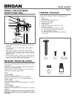
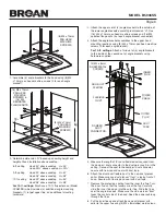
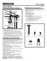
INSTALL THE DUCTWORK 
(Ducted Hoods Only)

1. Decide where the ductwork will run between the hood and 

the outside.

2. A straight, short duct run will allow the hood to perform 

most efficiently.

3.  Long duct runs, elbows and transitions will reduce the 

performance of the hood. Use as few of them as possible. 

Larger ducting may be required for best performance with 

longer duct runs.

4.  Install wall cap or roof cap. Connect round metal ductwork 

to cap and work back towards the hood location. Use duct 

tape to seal the joints between ductwork sections.

MEASURE THE INSTALLATION

The minimum hood distance above cooktop MUST NOT BE 

LESS than 30”. 
A maximum of 36” above cooktop is highly recommended for 

best capture of cooking impurities.


Distances over 36” are at the installer and users discretion; 

providing that the ceiling height permits.

NOTE:
On 8-ft. ceilings

Hood distance above cooktop is:

Minimum 30”, Maximum 32¼” (for ducted discharge)

Minimum 30”, Maximum 30½” (for non-ducted discharge)
On 9-ft. ceilings

Hood distance above cooktop is:

Minimum 30”, Maximum 36” (for both ducted and non-ducted 

discharge).
On 10-ft. ceilings

Hood distance above cooktop is:

Minimum 30”, Maximum 36” (for both ducted and non-ducted 

discharge).
NOTE: 10-ft. ceilings require 10-ft. Flue Extension, Model 

FXN59SS for ducted or non-ducted installations (purchase 

separately).

PREPARE THE HOOD

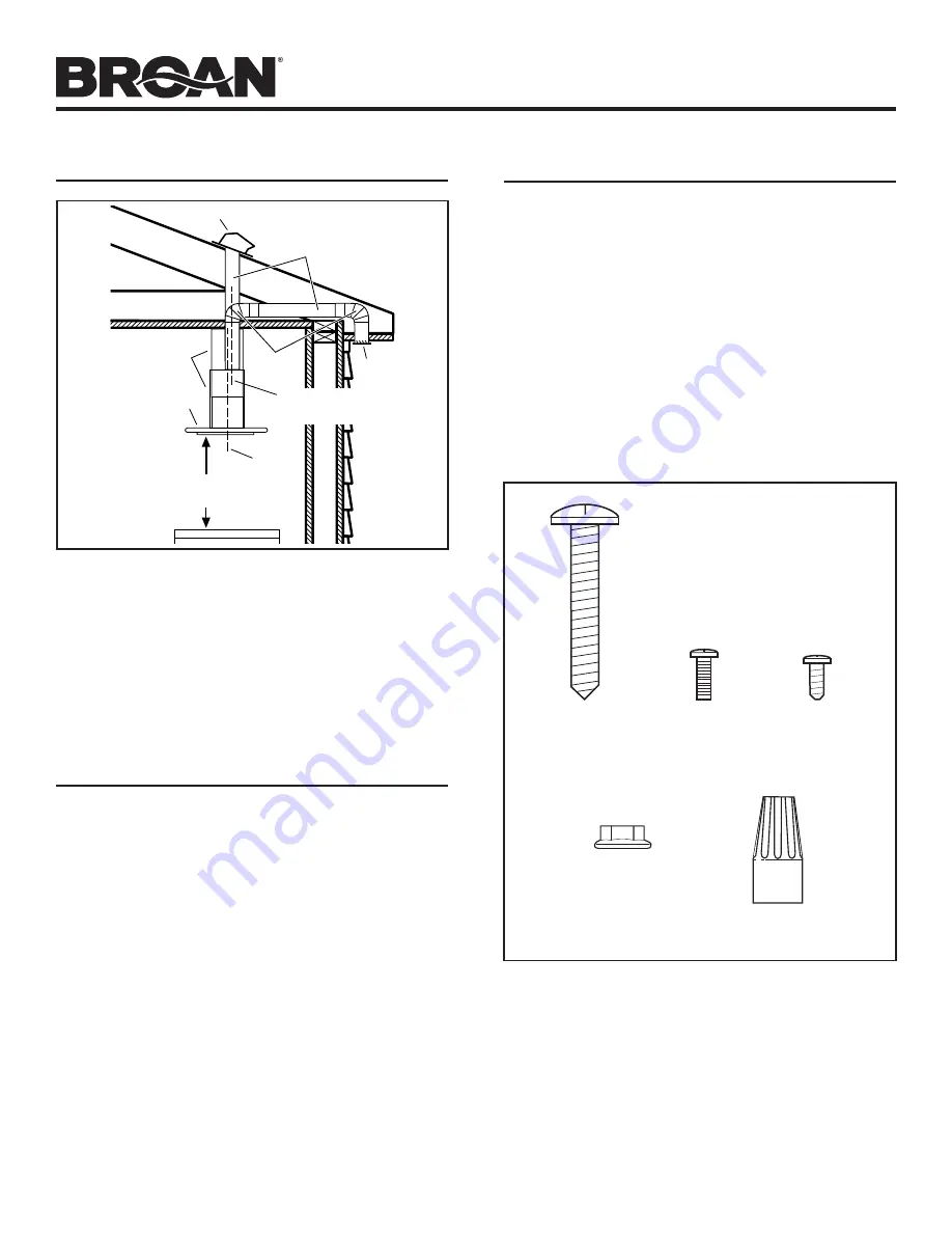
ROOF


CAP

DECORATIVE

FLUES

EAVE
VENT

6” ROUND

ELBOWS

6” ROUND

DUCT

HOOD

30” TO 36” ABOVE

COOKING SUFACE

HOOD

CENTER

LINE

DUCT CENTER LINE

(1-3/4” to rear of hood 

centerline)

Unpack hood and check contents. You should receive:
1 - Hood
1 - Metal Canopy
1 - Decorative Flue Assembly (2 pcs.)
1 - Damper / Duct Connector
1 - Ceiling Mounting Plate
8 - Angle Brackets
2 - Aluminum Grease Filters (installed in hood)
1 - Parts Bag containing:

8 - Mounting Screws (M6 x 40mm Pan Head)
46 - Machine Screws (M4 x 8mm Pan Head)
20 - Serrated Flange Nuts (M4)
8 - Sheet Metal Screws (M4 x 8mm Phillips Head)
3 - Wire Nuts

M4 x

8 mm

M4 x 8 mm

Sheet Metal

M6 x

40 mm

Wire Nut

M4

Serrated

Flange

Nut

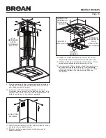
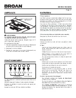
Summary of Contents for B5936SS

Page 1: ...e allowed to accumulate on fan or filters d Use proper pan size Always use cookware appropriate for the size of the surface element WARNING TO REDUCE THE RISK OF INJURY TO PERSON S IN THE EVENT OF A RANGE TOP GREASE FIRE OBSERVE THE FOLLOWING 1 SMOTHER FLAMES with a close fitting lid cookie sheet or metaltray thenturnofftheburner BECAREFULTOPREVENT BURNS IF THE FLAMES DO NOT GO OUT IMMEDIATELY EVA...

Page 2: ... is Minimum 30 Maximum 32 for ducted discharge Minimum 30 Maximum 30 for non ducted discharge On 9 ft ceilings Hood distance above cooktop is Minimum 30 Maximum 36 for both ducted and non ducted discharge On 10 ft ceilings Hood distance above cooktop is Minimum 30 Maximum 36 for both ducted and non ducted discharge NOTE 10 ft ceilings require 10 ft Flue Extension Model FXN59SS for ducted or non du...

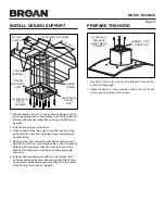
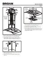
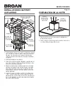
Page 3: ...nting plate and into electrical outlet box Secure house wiring cable to mounting plate electrical box with appropriate connector 5 Install ceiling mounting plate with the side marked front at the desired hood location Secure using 8 M6 x 40mm wood screws Make sure screws are driven into the center of the framing for maximum strength 1 Place the hood on flat surface with protection to insure the ho...

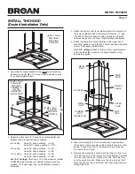
Page 4: ...on H based upon ceiling height and height of hood installation above cooktop 8 ft ceiling Hood 30 above cooktop H 30 Hood 32 above cooktop H 27 9 ft ceiling Hood 30 above cooktop H 42 Hood 36 above cooktop H 36 10 ft ceiling Hood 30 above cooktop H 54 Hood 36 above cooktop H 48 For 10 ft ceilings Purchase a 10 ft flue extension Model FXN59SS which includes 4 additional angle mounting brackets 1 lo...

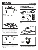
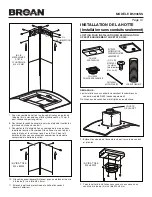
Page 5: ...ng and secure with 4 M4 x 8mm sheet metal screws 11 Remove the protective coating from the hood and the outer flue 4 M4 x 8mm SHEET METAL SCREWS INSTALL THE HOOD Non Ducted Installation Only NON DUCT PLENUM 2 TIE WRAPS FLEXIBLE DUCT NON DUCTED RECIRCULATION FILTER NON DUCT PLENUM COLLAR 8 MOUNTING SCREWS M4 x 8 Pan Head Sheet Metal FRONT NOTE Non ducted installations require Non Duct kit model RK5...

Page 6: ... HEAD MACHINE SCREWS 1 Assemble 4 angle brackets to the hood using 8 M4 x 10mm pan head machine screws 2 for each angle bracket 2 Determine dimension H based upon ceiling height and height of hood installation above cooktop 8 ft ceiling Hood 30 above cooktop H 30 Hood 30 above cooktop H 29 9 ft ceiling Hood 30 above cooktop H 42 Hood 36 above cooktop H 36 10 ft ceiling Hood 30 above cooktop H 54 H...

Page 7: ...metal screws 12 Remove the protective coating from the hood and the outer flue 4 M4 x 8mm SHEET METAL SCREWS 13 Remove the grease filters by pulling down the metal latch tab and tilting the filters downward to remove 14 Install the non duct recirculation filter as shown Turn mounting tabs on hood to secure filter 15 Reinstall grease filters by aligning rear filter tabs with slots in the hood Pull ...

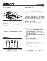
Page 8: ...ormance This discoloration is not covered by the warranty Non Duct Recirculation Filter Change the non duct recirculation filter every 6 months Hood Cleaning How to maintain the bright look of stainless steel and help prevent corrosion Dos Once a month wash surfaces with clean cloth or rag soaked with warm water and mild soap or liquid dish detergent Always clean in the direction of original polis...

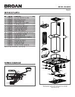
Page 9: ...al Plate with Rail 1 9 S99526983 Damper Duct Connector 1 10 S99526984 6 Dia Expandable Flexible Aluminum Duct 1 11 S99527021 Non Duct Plenum Assembly 1 12 S99527130 Angle Mounting Bracket 8 13 S99527022 Ceiling Mounting Bracket w Outlet Box 1 14 S99527013 Plastic Cover 1 S99527011 Transformer not shown 1 S99527012 Capacitor not shown 1 S99527132 Parts Bag not shown 1 S99528459 Non Duct Filter Clip...

Page 10: ...ée Utilisez toujours une batterie de cuisine adaptée à la dimension de la surface chauffante AVERTISSEMENT OBSERVEZ LES CONSIGNES SUIVANTES AFIN DE RÉDUIRE LES RISQUES DE BLESSURES CORPORELLES EN CAS D INCENDIE CAUSÉ PAR DE LA GRAISSE SUR LE PLAN DE CUISSON 1 ÉTOUFFEZ LES FLAMMES à l aide d un couvercle étanche d une tôle à biscuits ou d un plateau en métal puis éteignez le brûleur FAITES ATTENTIO...

Page 11: ...ne sortie sans conduits Plafonds de 2 7 m 9 pi La distance de la hotte au dessus de la surface de cuisson est Au minimum 76 cm 30 po au maximum 91 4 cm 36 po pour une sortie avec ou sans conduits Plafonds de 3 m 10 pi La distance de la hotte au dessus de la surface de cuisson est Au minimum 76 cm 30 po au maximum 91 4 cm 36 po pour une sortie avec ou sans conduits REMARQUE Les plafonds de 3 m 10 p...

Page 12: ...e de la plaque de fixation jusque dans la boîte de jonction Fixez le câble à la plaque boîte de jonction avec un con necteur approprié 5 Installez la plaque de fixation au plafond le côté marqué front avant orienté dans la bonne direction Fixez la plaque avec 8 vis à bois M6 x 40 mm Assurez vous que les vis sont enfoncées au centre des pièces de charpente pour une solidité maximale 1 Placez la hot...

Page 13: ... M4 x 10 mm et 16 écrous à embase dentelée M4 4 à chaque raccord d angle 4 Fixez l ensemble de supports aux emplacements de montage supérieurs de la hotte à l aide de 8 vis mécaniques à tête cylindrique M4 x 10 mm 2 pour chaque support angulaire Pour les plafonds de 3 m 10 pi Fixez un troisième ensemble de 4 supports angulaires à l intérieur du deuxième ensemble de supports à l aide de la quincail...

Page 14: ...fixez le à l aide de 4 vis à tôle M4 x 8 mm 11 Enlevez la pellicule protectrice de la hotte et du conduit décoratif extérieur 4 VIS À TÔLE M4 x 8 MM INSTALLATION DE LA HOTTE Installation sans conduits seulement CAISSON NON CANALISÉ 2 ATTACHES AUTOBLOCANTES CONDUIT FLEXIBLE FILTRE DE RECIRCULATION POUR INSTALLATION SANS CONDUIT COLLIER DE CAISSON NON CANALISÉ 8 VIS DE MONTAGE vis à tôle à tête cyli...

Page 15: ... cylindrique M4 x 10 mm 2 pour chaque support angulaire 2 Déterminez la dimension H d après la hauteur du plafond et celle de l emplacement de la hotte au dessus du plan de cuisson H 3 16 VIS MÉCANIQUES À TÊTE CYLINDRIQUE M4 x 10 MM ET 16 ÉCROUS À EMBASE DENTELÉE M4 8 VIS MÉCANIQUES À TÊTE CYLINDRIQUE M4 x 10 MM 3 Fixez l ensemble de 4 supports angulaires à l extérieur des supports angulaires du b...

Page 16: ...M4 x 8 mm 12 Enlevez la pellicule protectrice de la hotte et du conduit décoratif extérieur 4 VIS À TÔLE M4 x 8 MM 13 Enlevez les filtres à graisse en tirant vers le bas sur leur languette métallique et en basculant les filtres vers le bas 14 Installez le filtre de recirculation tel qu il est illustré Tournez les loquets de retenue de la hotte pour fixer le filtre 15 Pour remettre les filtres à gr...

Page 17: ...écoloration n est pas couverte par la garantie Filtre de recirculation pour installation sans conduits Remplacez le filtre de recirculation tous les six mois Nettoyage de la hotte Comment maintenir le lustre de l acier inoxydable et éviter la corrosion À faire Une fois par mois nettoyez toutes les surfaces avec un chiffon propre imbibé d eau tiède et de savon doux ou de liquide à vaisselle Nettoye...

Page 18: ... de conduit 1 10 S99526984 Conduit d aluminium flexible extensible 1 de 15 2 cm 6 po de diamètre 11 S99527021 Ensemble de caisson non canalisé 1 12 S99527130 Support angulaire 8 13 S99527022 Plaque de fixation au plafond avec boîte de jonction 1 14 S99527013 Couvercle en plastique 1 S99527011 Transformateur non illustré 1 S99527012 Condensateur non illustré 1 S99527132 Sachet de pièces non illustr...

Page 19: ...os ventiladores No permita la acumulación de grasa en el ventilador ni en los filtros d Use una cacerola del tamaño adecuado Siempre use utensilios de cocina que sean apropiados para el tamaño del elemento de la superficie ADVERTENCIA PARA REDUCIR EL RIESGO DE LESIONES PERSONALES EN EL CASO DE QUE LA GRASA DE LA ESTUFA SE INCENDIE OBSERVE LAS SIGUIENTES PRECAUCIONES 1 APAGUE LAS LLAMAS con una tap...

Page 20: ...ra la descarga sin conductos En los cielos rasos de 9 pies 2 7 m La distancia de la campana arriba de la estufa es Mínima de 30 pulg 76 cm máxima de 36 pulg 91 4 cm para la descarga para sistemas sin conductos y con conductos En los cielos rasos de 10 pies 3 m La distancia de la campana arriba de la estufa es Mínima de 30 pulg 76 cm máxima de 36 pulg 91 4 cm para la descarga para sistemas sin cond...

Page 21: ...xiones eléctricas Asegure el cableado de la casa a la placa de montaje caja eléctrica con el conector adecuado 5 Instale la placa de montaje del cielo raso con el lado marcado FRONT frente en la ubicación deseada de la campana Asegure usando 8 tornillos de madera M6 x 40 mm Asegúrese de que los tornillos se coloquen al centro de la estructura para obtener la máxima fuerza 1 Coloque la campana sobr...

Page 22: ...de máquina M4 x 10 mm de cabeza troncocónica y 16 tuercas de reborde serrado M4 4 en cada conexión de soporte en ángulo 4 Fije los conjuntos de soportes en ángulo sobre las ubicaciones superiores de montaje de la campana usando 8 tornillos de máquina M4 x 10 mm de cabeza troncocónica 2 para cada soporte en ángulo Para cielos rasos de 10 pies 3 m Fije un tercer juego de 4 soportes en ángulo al inte...

Page 23: ... 11 Retire el recubrimiento protector de la campana y el tubo de humos exterior 4 TORNILLOS DE CHAPA METÁLICA M4 x 8 MM INSTALE LA CAMPANA Únicamente en instalaciones sin conductos PLENO PARA SISTEMAS SIN CONDUCTOS 2 AMARRES CONDUCTO FLEXIBLE FILTRO DE RECIRCULACIÓN PARA SISTEMAS SIN CONDUCTOS COLLARÍN DEL PLENO PARA SISTEMAS SIN CONDUCTOS 8 TORNILLOS DE MONTAJE M4 x 8 chapa metálica de cabeza tro...

Page 24: ...e máquina M4 x 10 mm de cabeza troncocónica 2 para cada soporte en ángulo 2 Determine la dimensión H con base en la altura del cielo raso y la altura de la instalación de la campana arriba de la estufa H 3 16 TORNILLOS DE MÁQUINA M4 x 10 MM DE CABEZA TRONCOCÓNICA Y 16 ARANDELAS DE REBORDE SERRADO M4 8 TORNILLOS DE MÁQUINA M4 x 10 MM DE CABEZA TRONCOCÓNICA 3 Fije el conjunto superior de 4 soportes ...

Page 25: ...a y el tubo de humos exterior 4 TORNILLOS DE CHAPA METÁLICA M4 x 8 MM 13 Retire los filtros de grasa estirando hacia abajo la cejilla metálica e inclinando los filtros hacia abajo para quitarlos 14 Instale el filtro de recirculación para sistemas sin conductos como se muestra Gire las lengüetas de montaje en la campana para asegurar el filtro 15 Reinstale los filtros para grasa alineando las lengü...

Page 26: ...miento del filtro Esta decoloración no está cubierta por la garantía Filtro de recirculación para sistemas sin conductos Cambie el filtro de recirculación cada 6 meses Limpieza de la campana Cómo mantener el aspecto brillante del acero inoxidable y ayudar a prevenir la corrosión Cosas qué hacer Una vez al mes lave las superficies con una tela o trapo limpio remojado con agua tibia y jabón o deterg...

Page 27: ...egulador de tiro conducto 1 10 S99526984 6 pulg 15 2 cm de diám Conducto de aluminio 1 flexible expansible 11 S99527021 Conjunto del pleno para sistemas sin conductos 1 12 S99527130 Soporte para montaje en ángulo 8 13 S99527022 Soporte de montaje para cielo raso con caja 1 de conexiones 14 S99527013 Cubierta de plástico 1 S99527011 Transformador no se muestra 1 S99527012 Capacitor no se muestra 1 ...

Page 28: ...riction ne s applique pas dans votre cas LE REMPLACEMENT OU LA RÉPARATION PAR BROAN NUTONE À SA PROPRE DISCRÉTION DE TOUT PRODUIT OU PIÈCE DÉFECTUEUX CONSTITUE LE SEUL REMÈDE DE L ACHETEUR EN VERTU DE CETTE GARANTIE BROAN NUTONE NE PEUT ÊTRE TENUE RESPONSABLE DES DOMMAGES INDIRECTS CONSÉCUTIFS OU SPÉCIAUX ATTRIBUABLES À UTILISATION OU AU RENDEMENT DU PRODUIT Certains États ne recon naissent pas le...

Reviews: