background image

MODELS EWT1306SS • EWT1366SS

Page 3

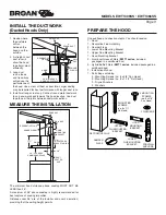
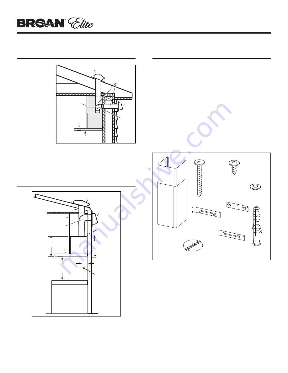
INSTALL THE DUCTWORK 

(Ducted Hoods Only)

1. Decide where 

the ductwork 
will run 
between the 
hood and the 
outside.

2. A straight, short 

duct run will 
allow the hood 
to perform most 
efficiently.

3.   Long  duct 

runs, elbows 
and transitions 
will reduce the 
performance of 
the hood. Use as few of them as possible. Larger ducting 
may be required for best performance with longer duct runs.

4.  Install wall cap or roof cap. Connect round metal ductwork 

to cap and work back towards the hood location. Use duct 
tape to seal the joints between ductwork sections.

MEASURE THE INSTALLATION

The minimum hood distance above cooktop MUST NOT BE 
LESS than 26”.
A maximum of 36” above cooktop is highly recommended for 
best capture of cooking impurities. 
Distances over 36” are at the installer and user's discretion; 
providing that the ceiling height permits. 

6"

ROUND DUCT

ROOF CAP

ROUND

ELBOW

26" MIN. ABOVE

COOKING SURFACE

WALL

CAP

HOOD

DECORATIVE

FLUE

HH0302A

10-1/2”

WALL CAP

26” - 36” ABOVE

COOKING SURFACE

HOOD

DECORATIVE FLUE

ROOF CAP

6” ROUND DUCT

ROUND ELBOW

11-7/8”

TO CENTER OF

BRACKET HOLES

HOOD 
MOUNTING
BRACKET

3-3/8”

DUCT

CENTER

LINE

HH0303A

PREPARE THE HOOD

Unpack hood and check contents. You should receive:
1 - Hood
1 - Decorative Flue Assembly
2 - Damper Flaps
1 - Lower Flue Mounting Bracket
1 - Upper Flue Mounting Bracket
1 - Hood Mounting Bracket
2 - Aluminum Grease Filters (

EWT1 series

, included  


packaged in a cardboard box)

2 - Hybrid Baffle Filters (

EWT1 series

, included packaged in a  


cardboard box)

1 - Installation Manual
1 - Parts Bag containing:
 

4 - Mounting Screws (no. 8 x 3/8” Pan Head)


9 - Mounting Screws (no. 8 x 1-1/2” Flat Head)


9 - Drywall Anchors


2 - Washers

7 MOUNTING
SCREWS
(no. 8 x 1½”
Flat Head)

7 DRYWALL

ANCHORS

4  MOUNTING

SCREWS

(no. 8 x 3/8”

Pan Head)

DECORATIVE FLUE

2  WASHERS

UPPER

FLUE MOUNTING

BRACKET

HOOD

MOUNTING

BRACKET

LOWER

FLUE MOUNTING

BRACKET

DAMPER

FLAPS

HR0258A

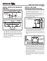
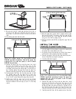
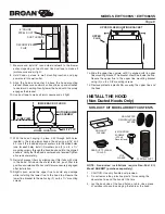
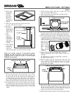
11½’’

9

9

Summary of Contents for EWT1306SS

Page 1: ...requently Grease should not be allowed to accumulate on fan or filters d Use proper pan size Always use cookware appropriate for the size of the surface element WARNING TO REDUCE THE RISK OF INJURY TO PERSON S IN THE EVENT OF A RANGE TOP GREASE FIRE OBSERVE THE FOLLOWING 1 SMOTHER FLAMES with a close fitting lid cookie sheet or metaltray thenturnofftheburner BECAREFULTOPREVENT BURNS IF THE FLAMES ...

Page 2: ...e hood During construction renovation cover the range hood to make sure no dust sticks to the stainless steel surface Avoid When choosing a detergent Any cleaners that contain bleach will attack stainless steel Any products containing chloride fluoride iodide bromide will deteriorate surfaces rapidly Any combustible products used for cleaning such as acetone alcohol ether benzol etc are highly exp...

Page 3: ...ceiling height permits 6 ROUND DUCT ROOF CAP ROUND ELBOW 26 MIN ABOVE COOKING SURFACE WALL CAP HOOD DECORATIVE FLUE HH0302A 10 1 2 WALL CAP 26 36 ABOVE COOKING SURFACE HOOD DECORATIVE FLUE ROOF CAP 6 ROUND DUCT ROUND ELBOW 11 7 8 TO CENTER OF BRACKET HOLES HOOD MOUNTING BRACKET 3 3 8 DUCT CENTER LINE HH0303A PREPARE THE HOOD Unpack hood and check contents You should receive 1 Hood 1 Decorative Flu...

Page 4: ...iance is equipped with a cord with incorporated grounding wire with a grounding plug The plug must be plugged into an outlet that is properly installed and grounded NOTE A recessed clock outlet is recommended 2 Position the electrical outlet within the space covered by the decorative flue and where it will not interfere with the round duct Make sure the outlet does not interfere with the mounting ...

Page 5: ...nd flue length permit MOUNTING BRACKET LOCATION ABOVE 36 HIGH COOKTOP NOTE On 8 ft ceilings Hood distance above cooktop is Minimum 26 Maximum 36 for both ducted and non ducted discharge On 9 ft ceilings Hood distance above cooktop is Minimum 32 Maximum 36 for both ducted and non ducted discharge On 10 ft ceilings Hood distance above cooktop is Minimum 32 Maximum 36 for both ducted and non ducted d...

Page 6: ... the hood 3 Remove the grease filters by pulling down the metal latch tab and tilting filters downward to remove 4 Carefully rotate hood upright HD1258 INSIDE BACK OF HOOD MOTOR BLOWER ASSEMBLY HOLES LOCATION SIDE VIEW Ø5 16 TYP 5 To make sure there will be adequate clearance between top of hood and lower flue mounting bracket for ductwork Elbow must be located below lower flue mounting bracket 6 ...

Page 7: ...x 3 8 mounting screws 15 Remove protective plastic film covering the upper flue and the hood HO0366 UPPER FLUE UPPER FLUE MOUNTING BRACKET 8 8 6 ROUND DUCT ELBOW 9 Measure and install 6 round steel ductwork to roof cap or wall cap and 90o elbow over the blower exhaust opening on top of hood Use duct tape to make all joints secure and air tight 10 Plug hood power cord into the outlet INSTALL THE HO...

Page 8: ...nto position and release Make sure filters are securely engaged after installation 13 Slightly push aside the upper flue to avoid any damage while installing the lower flue to the hood top Secure the lower flue bracket to the wall using 2 no 8 x 1 mounting screws 14 Slide the upper flue upward until it is aligned with its upper flue mounting bracket The bracket should be inside the flue Secure the...

Page 9: ... 8 x 3 8 pan head screws 6 Measure distance A This will be the HD1181 HD1179 LOWER FLUE MOUNTING BRACKET LOWER FLUE 13 Align the hood and center it above the hood mounting bracket Gently lower the hood until it securely engages the bracket 14 With the hood hanging in place drill through both holes located in the inside lower back of hood using a 5 16 drill bit Insert the included drywall anchors i...

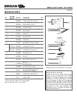
Page 10: ...ntact a certified service depot for all replacement parts and repairs B C D E F G H I J K L KEY CUSTOMER MODEL NO PART NO DESCRIPTION QTY 1 S99528454 Decorative Upper and Lower Flues 1 2 S99010497 Mounting Bracket set of 3 1 3 S99529088 Plastic box of PCB 1 4 S99010491 30 µf Capacitor 1 5 S1104711 Main PCB 1 6 S1104709 Control Assembly 1 7 S99010499 Damper flap 1 8 S1104710 600CFM Motor Blower Ass...

Page 11: ... freight charges incurred in the shipment of the Product or part to the Company If you must send the Product or part to the Company as instructed by the Company you must properly pack the Product or part the Company is not responsible for damage in transit The Company reserves the right to utilize reconditioned refurbished repaired or remanufactured Products or parts in the warranty repair or repl...

Reviews: