2
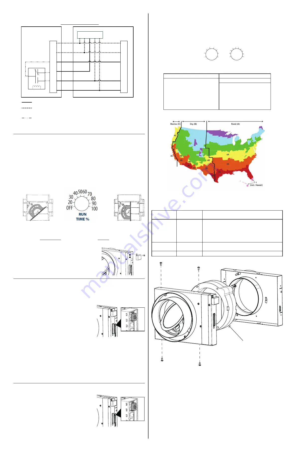
4.1 AHU W
iring
5. SETTING UP THE UNIT
When powered ON, the FIN-6MD performs a 30-second booting sequence followed by a 30-minute period
where is stays OFF, but will activate if a heating or cooling call is sent to the AHU.
Refer to local building codes to determine the required airflow.
1. Doublecheck the wiring, and turn power back ON to the AHU.
2. Set the thermostat to send a heating or cooling call, or jump R and Y on the terminal block. This will
force the ventilation ON for at least 5 minutes.
3. Measure the airflow.
If it needs adjustment, perform steps 4. If the airflow does not need adjustment, go to step 5.
4. The damper is factory set to fully open position. To adjust it, set the left pot to
DAMPER
ADJUSTMENT
to start the AHU blower, and wait 5 seconds. The LED will blink continuously to
indicate the unit is in DAMPER ADJUSTMENT mode.
While measuring the airflow, adjust the damper using the RUN TIME % pot until you’ve reached the
desired value.
5. Select the desired mode according to the table and map in section 7.3. Doing so also saves the
damper adjustment made in the previous step if applicable.
6. Set the RUN TIME %
pot.
7. Install the supplied cover to protect the adjustment pots and
prevent an accidental change of settings. Note that the hole may
be hidden by the label.
6. TESTING
When powered ON, the FIN-6MD performs a 30-second booting sequence followed by a 30-minute period
where it stays OFF, but will activate if a heating or cooling call is sent to the AHU.
6.1 B
loWer
door
test
(
force
tHe
dAmper
closed
)
If the access to the integrated switch OR to the remote switch (if
applicable) is
easy
, set the integrated switch OR remote switch to
OFF.
If the access to the switch is
not easy
, such as in an attic:
1. Turn OFF the power to the AHU at the service panel.
2. Turn the power to the AHU back ON at the service panel.
3. Wait 30 seconds for the booting sequence to execute.
4. Make sure that the thermostat will not send a heating or cooling
call.
5. Unit is OFF with its damper closed for 30 minutes, but will
activate if a heating or cooling call is sent to the AHU.
6.2 V
entilAtion
test
(
forcing
tHe
Unit
on):
1. Turn OFF the power to the AHU at the service panel, and make sure that the integrated or remote switch
is set to ON.
2. Turn the power back ON at the service panel.
3. Wait 30 seconds for the booting sequence to execute.
4. Set the thermostat to send a heating or cooling call,
or
jump R and Y on the terminal block. This will force
the ventilation ON for at least 5 minutes.
7. USER INFORMATION
7.1 i
ntegrAted
And
remote
sWitcHes
This unit is equipped with an integrated ON/OFF switch. For more
convenience, your FIN-6MD can also be connected to a remote
switch.
To use a remote switch, disconnect the integrated switch and
connect the remote switch in the same manner that the integrated
one was connected.
7.2 U
ser
s
erVicing
i
nstrUctions
• Inspect the outdoor air intake at least once a year.
• These recommendations may change according to the environmental conditions in your area.
Y
W
G
F
G
R
C
COM
NC
NO
Internal
Logic
CFIS
System
Y
W
G
R
C
Y W G R C
Thermostat
Optional Installation Wiring (Recommended if existing Y/W
connections are present at AHU)
FIN-6MD Hard Connections
AHU
AHU Wiring Options
J4
Mandatory Installation Wiring
Ref. : 1103507 rev. B
Damper
fully open
Damper
half open
Run time % = Required Airflow Example : Run Time % = 60 CFM = 50%
Measured Airflow
120 CFM
ON
Integrated switch
ON
Integrated switch
7.3 c
omfort
m
ode
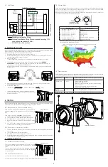
Should the air inside your house become too humid, or if such conditions want to be prevented, the operation
mode of your FIN-6MD can be changed from a Code-Compliant one (modes 1 and 2) to a Comfort Mode
(modes A to E). Refer to the map below to make the right choice.
When making such change, make sure to only change the Mode and to leave the Run time % as it was set by
your installer. If in doubt, refer to your HVAC contractor.
7.4 t
roUBlesHooting
A LED indicator is located to the right of the terminal block on the unit and communicates the different states
of the unit. Blinking patterns and ways to address them, if applicable, are as follows:
Sensor error
1 blink
Disconnect the terminal block, and connect again. If the error
persists, replace the unit.
Damper error
2 blinks
Disconnect the terminal block.
Open unit (see image below).
Perform a visual inspection and remove any debris hindering
damper movement.
Close unit and put the terminal block back in place.
If error persists, replace the unit.
Damper
adjustment mode
Continuous blink
This is normal while the unit is in adjustment mode.
Learning mode
1 s ON, 10 s OFF This is normal. Will blink for 48 hours after being powered ON.
VN0012A
5B
5A
Selected mode*
Climate Zones**
1
- Ashrae 2010/IRC/IMC (factory set)
Zones 1-5
2
- Ashrae 2016/2019
Zones 1-5
A
- Comfort mode Hot / Humid #1
Zones 2A and 1
B
- Comfort mode Hot / Humid #2
Zones 1 and 2A
C
- Comfort mode Hot / Dry
Zone 2B
D
- Comfort mode Mixed / Humid
Zones 3A, 4A, 5A, 3C and 4C
E
- Comfort mode Mixed / Dry
Zones 3B, 4B and 5B
*Refer to the label on the unit for the full limits table.
**As defined by the Department of Energy.
OFF
20
30
405060 70
80
90
100
MODE
RUN
TIME %
Damper
adjustment
(wait 5 sec.)
1
2 A B C
D
E
*D
.P.: D
ew poin
t
Code modes:
1- ASHRAE 2010/IRC/IMC (factory set)
2- Ashrae 2016/2019
Comfort modes:
A- Hot / Humid #1
B- Hot / Humid #2
C- Hot / Dry
D- Mixed / Humid
E- Mixed / Dry
1- Set left pot to DAMPER
ADJUSTMENT.
2- Use right pot to adjust
damper from fully
open to half open.
3- Set the required mode
to save damper setting.
4- Set the RUN TIME% to
get the required
ventilation level.
D.P.*
D.P.*
D.P.*
D.P.*
T°
T°
T°
Lower limits (F)
Lower limits (F)
Upper limits (F)
Upper limits (F)
No thermostat call
Heating call
Cooling call
Selec
ted
mode
T°
1
78
80
85
80
80
96
98
102
90
95
14
14
14
14
14
32
32
32
32
32
-4
73
75
75
75
75
88
90
95
85
86
23
23
23
23
23
40
40
40
40
40
-4
A
B
C
D
E
2
Compliant - No limits
Compliant - No limits
-4
-4
Compliant - No limits
Compliant - No limits
Sensor Error
1 blink
2 blinks
Cont. blinks
1s ON &
10s OFF
Damper Error
Damper Adj.
Learning Mode
Broan-NuTone LLC Hartford, Wisconsin
www.broan-nutone.com 800-558-1711
Refer to installation instructions
for more details.
LED
SIGNAL
Switch
1103497B
AHU Wiring
SI
SO
R
I
G
GF W
Y
C
Internal insulation


