2
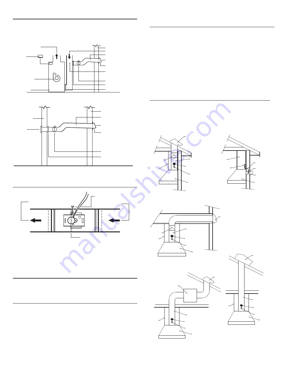
Damper and outside air duct connected directly to a ceiling, floor, or wall register.
INTERIOR WALL
WALL
REGISTER
REGISTER BOX ADAPTED
WITH SLIDE-IN FILTER (optional)
MOTORIZED DAMPER
WALL CAP WITH
BIRD SCREEN
INSULATED OUTSIDE
AIR DUCT (slope toward wall cap)
EXTERIOR WALL
VENTILATION AIR INTAKE
(locate away from pollutant sources)
TYPICAL INSTALLATIONS
Installations will vary according to the location in the home where the unit is installed
and which model Damper is used. Use the following illustrations and notes as guidance
for your own installation. Always comply with local code requirements and in any
instance where a detail shown below conflicts with local code, the local code provision
shall apply.
Damper connected to return side of central duct system.
AIR HANDLER UNIT
AIR DISTRIBUTION FAN
THERMOSTAT
CENTRAL SYSTEM SUPPLY AIR
REGISTER BOX ADAPTED
WITH SLIDE-IN FILTER (optional)
AUTO. MAKE-UP AIR DAMPER
FIELD MEASUREMENT OF AVAILABLE
STATIC PRESSURE. (See “Install The
Damper” section on page 3 for damper
balancing instructions.)
FRESH AIR INLET WALL CAP
WITH BIRD SCREEN
INSULATED OUTSIDE
AIR DUCT (slope toward wall cap)
EXTERIOR WALL
VENTILATION AIR INTAKE
(locate away from pollutant sources)
CENTRAL SYSTEM RETURN AIR
CENTRAL DUCT SYSTEM FILTER
INSTALL THE DAMPER
OUTSIDE AIR
TO CENTRAL SYSTEM
RETURN AIR OR INTERIOR
WALL REGISTER
DAMPER FLAP (Install in
vertical position shown.)
AIR FLOW
AIR FLOW
SET SCREW
Install the damper as shown. Make sure damper flap is in a vertical position when
closed and power is off. The set screw can be used to adjust the damper opening -
thereby balancing the inside and outside air pressure when the range hood exhausts
at high speed.
PRESSURE SWITCH OPERATION
The pressure switch is designed to operate when the static pressure increases to 0.05”
Ps or more. It may not operate at low speeds since the pressure is below this limit.
MULTIPLE DAMPERS
More than one damper may be required to balance the system. If more than one is
required use (1) MD6TU or MD8TU and then use the MD6 or MD8 dampers as ad-
ditional dampers.
INSTALLATION OF PRESSURE SWITCH
AND PROBE
For the probe & pressure switch to work effectively the roof or wall cap must have a
spring loaded damper. The following Broan products are recommended:
TYPICAL INSTALLATION WITH
INTERNAL BLOWER AND ROOF VENT
RANGE
HOOD
PROBE
EXHAUST
DUCT
ROOF CAP
w/DAMPER
PRESSURE
SWITCH
HOOD
FLUE
IN-LINE
DAMPER
TYPICAL INSTALLATION WITH
INTERNAL BLOWER AND WALL VENT
RANGE
HOOD
PROBE
EXHAUST
DUCT
PRESSURE
SWITCH
HOOD
FLUE
WALL CAP
w/DAMPER
IN-LINE
DAMPER
TYPICAL INSTALLATION WITH
INTERNAL BLOWER AND HORIZONTAL
DUCTING w/ WALL VENT
RANGE
HOOD
WALL CAP
w/DAMPER
PROBE
TUBING
PRESSURE
SWITCH
KITCHEN
CABINET
TYPICAL INSTALLATION WITH INLINE BLOWER
RANGE
HOOD
PROBE
EXHAUST
DUCT
PRESSURE
SWITCH
HOOD
FLUE
ROOF CAP
w/DAMPER
INLINE
BLOWER
TYPICAL INSTALLATION
WITH EXTERIOR BLOWER
RANGE
HOOD
PROBE
EXHAUST
DUCT
PRESSURE
SWITCH
HOOD
FLUE
EXTERIOR
BLOWER
Wall Cap models:
WC638 – For 3¼” x 14” duct
639 / 649 – For 3¼” x 10” duct
647 – For 7” round duct
843BL / 641 – For 6” round duct
643 / 643FA – For 8” round duct
613 – For 12” round duct
441 – For 10” round duct.
Roof Cap models:
437 – High capacity up to
1200 cfm
634 / 644 – For 3¼” x 10” and
up to 8” round
634M – For 6” round
LOCATION OF PROBE AND
PRESSURE SWITCH
The probe must be mounted between the range hood damper and the wall cap, roof
cap, in-line blower or external blower. Mount the probe as close to the hood outlet as
possible but make sure the hood damper operation is not affected.
The pressure switch should be mounted so it is accessible for any future service.
The switch can mounted no more then 72” away from the probe. If longer tubing is
required then what is supplied, purchase 1/4” I.D. PVC tubing from a local source.
See the illustrations below for possible installation scenarios.


