MODELS MD6TR • MD8TR
Page 4
Once the Damper and the associated Broan or BEST exhaust
devices are installed, the installer should confirm that the Damper
opens and closes in conjunction with signals from the exhaust
devices(s) as intended.
A qualified HVAC contractor should also ensure the proper
operation and venting of all combustion equipment in the home.
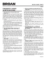
SYSTEM OPERATION
Regular maintenance is necessary to ensure the proper operation
of the Damper system. Failure to conduct such routine mainte-
nance can jeopardize the ability of the Damper to introduce fresh
air into the home. Regular maintenance should include the follow-
ing activities:
• Clean the outside bird screen to ensure it is free from debris
and open to allow fresh air to enter.
• Clean or replace the interior filter(s) which serve to filter fresh air
before it enters the home.
• Maintain a clear opening at the outdoor end cap, which means
preventing the buildup of snow, leaves, or vegetation at the end
cap.
• During regular HVAC maintenance, have the mechanical con-
tractor inspect the Damper system for proper operation.
MAINTENANCE
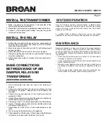
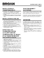
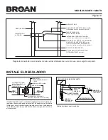
INSTALL THE TRANSFORMER
1. Make sure power to the transformer is disconnected at the
service entrance before installation.
2. Secure the transformer to an appropriately sized junction box.
3. Connect white-to-white, black-to-black and green-to ground.
Install junction box cover.
INSTALL THE RELAY
1. Position the relay behind the decorative flue, approximately 6”
above the top of the range hood. Make sure its final location
clears the sheet metal duct.
2. Mark its location on the wall and install (2) self drilling drywall
anchors provided.
3. Secure the relay to the wall with (2) # 6 screws provided.
4. Remove insulating caps from the two wires marked “make-up
air system connection”.
5. Attach these wires to the (2) smallest 3/16” wide terminals on
the relay.
MAKE CONNECTIONS
BETWEEN MAKE-UP AIR
DAMPER, RELAY AND
TRANSFORMER
(SEE WIRING SCHEMATIC)
1. Run 20 gauge bell wire from the relay to the make-up air
damper.
2. Connect one bell wire from the relay to one brown wire from
the make-up air damper. Secure with a wire connector (not
provided).
3. Connect the second bell wire to the transformer terminal
marked 24V 20VA.
4. Connect the second brown wire from the make-up air damper to
the transformer terminal marked 24V 20VA.
5. At the relay, strip ¼” of insulation from both ends of the bell wire.
6. Install ¼” female quick connect terminals provided and crimp
with pliers or crimping tool.
7. Attach these (2) wires to the ¼” wide male terminals on the
relay.
8. Turn on power to the transformer and rangehood.
9. Check operation of the damper. It should open when the blower
is turned on and close when the blower is turned off.


