background image

QP2 SERIES

Page 6

16 

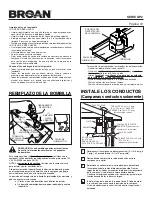
DUCTED INSTALLATION ONLY:

Remove 3¼” x 10 vertical, 3¼” x 10” horizontal, or 7-inch 

round 

knockout plate(s)

 as appropriate for your ducting 

method.

3¼” X 10”

HORIZONTAL

KNOCKOUT

PLATE

3¼” X 10”

VERTICAL

KNOCKOUT

PLATE

7” ROUND

KNOCKOUT

PLATE (also 

remove 3¼” x 10” 

vertical plate)

7” ROUND 

DUCT 

PLATE

INSTALL THE HOOD

19 

Run 

House Power Cable

 between service panel and hood 

location. Attach power cable to hood using appropriate clamp.

20 

Hang hood from (4) mounting screws driven part-way into 

cabinet locations (shown in illustrations under 

“PREPARE 

HOOD LOCATION”

). Mounting screws are included in parts 

bag. Slide hood back towards wall until mounting screw 

heads are engaged in narrow end of keyhole slots in top of 

hood. Tighten screws securely. Add 5th mounting screw in 

center hole in hood and tighten securely.

21 

DUCTED INSTALLATION ONLY:

Connect ductwork to hood and use duct tape to make joints 

secure and air-tight.


Make sure the damper / duct connector 

enters the ductwork and that the damper opens and closes 

freely.

HOUSE

POWER CABLE

WARNING


To reduce the risk of electrical shock, switch power off  


at service panel. Lock or tag service panel to prevent    


power from being switched on accidentally.

ELECTRICAL 

WIRING BOX 

COVER

18 

Remove 

Electrical Wiring Box Cover

 from inside 

of hood and appropriate 

Electrical Power Cable 

Knockout

 from top or back of hood.

ELECTRICAL 

POWER

CABLE

KNOCKOUT

17 

DUCTED INSTALLATION ONLY:

Attach 

3¼” x 10” Damper/Duct Connector

 (if using 3¼” 

x 10” duct) or 

7” Round Duct Plate

 (if using 7-inch round 

duct) over the knockout opening.

Notes:

To accomodate off-center ductwork, the 3¼” x 10” 

damper/duct connector can be installed up to ½” on either 

side of the hood center and the 7” round duct plate can 

be installed up to ½” on either side of the hood center.
Install the 3¼” x 10” Damper/Duct Connector with the 

Damper Flap Pivot

 nearest the 

Top/Back Edge of 

Hood

.

TOP/BACK

EDGE OF

HOOD

DAMPER

FLAP

PIVOT

3¼” X 10”

DAMPER / 

DUCT 

CONNECTOR

Summary of Contents for QP2 SERIES

Page 1: ...hould not be al lowed to accumulate on fan or filter 4 Use proper pan size Always use cookware appropriate for the size of the surface element TO REDUCE THE RISK OF INJURY TO PERSONS IN THE EVENT OF A RANGE TOP GREASE FIRE OBSERVE THE FOLLOWING 1 SMOTHER FLAMES with a close fitting lid cookie sheet or metal tray then turn off the burner BE CAREFUL TO PREVENT BURNS If the flames do not go out immed...

Page 2: ... when the temperature is above normal When the Heat Sentry system is on the light above the high speed fan button will flash on and off After the temperature has lowered to normal the fan speed will be reduced until the temperature has stabilized then the fan will turn off FUSE The Range Hood Control Board contains a Fuse to protect the controls from power surges If the fuse has opened blown the g...

Page 3: ...clockwise until firmly seated The position of the bulb socket depth is adjustable and may require adjustment when a certain brands of bulbs are difficult to install b the bulb protrudes too far below the light panel 1 PUSH IN CAUTION Bulbs may be hot Always allow bulbs to cool down before removing them 2 ROTATE CLOCKWISE SUCTION CUP TOOL HALOGEN BULB LIGHT PANEL SCREWS LIGHT PANEL SOFFIT 24 30 ABO...

Page 4: ...T BOTTOM 17 5 8 42 hood 4 21 8 25 8 11 67 8 17 5 8 42 hood 14 5 8 36 hood 14 5 8 36 hood 11 5 8 30 hood 11 5 8 30 hood 3 X 10 VERTICAL DUCTING Note the extra wood shim and mounting screw near the cabinet front on the cabinet center line CONTENTS GREASE FILTERS 2 FOR 30 36 HOODS 3 FOR 42 HOODS 1 3 X 10 DAMPER DUCT CONNECTOR 1 7 ROUND DUCT CONNECTOR 4 HALOGEN BULBS 1 BULB SUCTION CUP TOOL 1 PARTS BA...

Page 5: ...holding Non Duct Plate to Non Duct Plenum and remove plate 14 NON DUCTED INSTALLATION ONLY Insert short end of Non Duct Plate into Non Duct Plenum Slot Attach with 2 Screws removed in Step 13 SCREWS SCREWS NON DUCT PLATE NON DUCT PLENUM NON DUCT PLATE ç SLOT 11 Remove 2 Screws holding Damper Duct Connector to hood Remove damper duct connector from inside the hood FOR DUCTED INSTALLATIONS Skip to S...

Page 6: ...use duct tape to make joints secure and air tight Make sure the damper duct connector enters the ductwork and that the damper opens and closes freely HOUSE POWER CABLE WARNING To reduce the risk of electrical shock switch power off at service panel Lock or tag service panel to prevent power from being switched on accidentally ELECTRICAL WIRING BOX COVER 18 Remove Electrical Wiring Box Cover from i...

Page 7: ...year period as specified for the express warranty Some states do not allow limitation on how long an implied warranty lasts so the above limitation may not apply to you BROAN NUTONE S OBLIGATION TO REPAIR OR REPLACE AT BROAN NUTONE S OPTION SHALL BETHE PURCHASER S SOLE AND EXCLUSIVE REMEDY UNDER THIS WARRANTY BROAN NUTONE SHALL NOT BE LIABLEFORINCIDENTAL CONSEQUENTIALORSPECIAL DAMAGES ARISING OUT ...

Page 8: ...cludes mounting hardware 10 97018229 Light Panel LH White includes mounting hardware 97018230 Light Panel LH Black includes mounting hardware 97018231 Light Panel LH Stainless includes mounting hardware 97018232 Light Panel LH Bisque includes mounting hardware 11 97017731 Lamp Socket includes lamp socket wire nuts mounting screws 12 97018233 Lamp Socket Bracket 13 97018236 Bottom Pan 30 includes m...

Page 9: ... les filtres ou dans les conduits d évacuation 4 Utilisez le bon format de casserole Servez vous toujours de casseroles et d ustensiles appropriés à la dimension de la surface chauffante LIRE ET CONSERVER CES DIRECTIVES POUR USAGE RÉSIDENTIEL SEULEMENT AVERTISSEMENT AFIN D ÉVITERTOUT RISQUE DE BLESSURES DANS LE CAS D UN FEU DE CUISINIÈRE SUIVEZ CES DIRECTIVES 1 Étouffez les flammes avec un couverc...

Page 10: ...in lumineux au dessus du bouton poussoir de la haute vitesse clignote Une fois la température revenue à la normale la vitesse du ventilateur baisse jusqu à ce que la température se stabilise puis le ventilateur s arrête NETTOYAGE ET ENTRETIEN La hotte doit être entretenue de façon appropriée afin de s assurer des meilleures performances possibles Moteur Le moteur est lubrifié à vie Ne pas huiler S...

Page 11: ...e à la verticale 3 po x 10 po ou 7 po rond ou à l horizontale 3 po x 10 po seulement INSTALLATION DES CONDUITS installation avec conduit seulement 2 Déterminer par où passera le conduit entre votre hotte et l extérieur 3 Un conduit droit et court permettra à votre hotte de fonctionner plus efficacement Un conduit long avec des coudes et des transitions réduira la performance de votre hotte En util...

Page 12: ...nduit et le fil d alimentation électrique selon l évacuation choisie horizontale ou verticale Voir les illustrations ci dessous Pour une installation en recirculation NE PAS découper d ouverture pour le conduit CONDUIT VERTICAL 3 PO X 10 PO CONDUIT ROND DE 7 PO Languettes de bois et vis supplémentaire près de l avant de l armoire sur la ligne de centre de l armoire PRÉPARATION DE L EMPLACEMENT FIL...

Page 13: ... BAS 2 DEGAGER 9 Retirer les filtres d aluminium de la hotte 10 Retirer les six vis de retenue du panneau inférieur Mettre le panneau et les vis de côté 11 Retirer les deux vis de retenue de l adaptateur volet et le retirer de l intérieur de la hotte POUR LES INSTALLATIONS AVEC CONDUIT Passer à l étape 16 ADAPTATEUR VOLET 12 INSTALLATION EN RECIRCULATION SEULEMENT Fixer le déflecteur inclus dans l...

Page 14: ...a hotte Placer le pivot du volet de l adaptateur volet de 3 po x 10 po près du rebord supérieur arrière de la hotte REBORD SUPÉRIEUR ARRIÈRE DE LA HOTTE ADAPTATEUR VOLET DE 3 PO X 10 PO PIVOT DU VOLET COUVERCLE DU COMPARTIMENT ÉLECTRIQUE INSTALLATION DE LA HOTTE CÂBLAGE RÉSIDENTIEL OUVERTURE PRÉAMORCÉE DU FIL D ALIMENTATION ÉLECTRIQUE 18 Retirer le couvercle du compartiment électrique à l intérieu...

Page 15: ... la garantie expresse Certains États et provinces ne reconnaissent pas les restrictions relatives à la durée des garanties implicites il se pourrait donc que cette restriction ne s applique pas dans votre cas LE REMPLACEMENT OU LA RÉPARATION PAR Broan NuTone À SA PROPRE DISCRÉTION DE TOUT PRODUIT OU PIÈCE DÉFECTUEUX CONSTITUE LE SEUL REMÈDE DE L ACHETEUR EN VERTU DE CETTE GARANTIE Broan NuTone NE ...

Page 16: ...age 10 97018229 Panneau d éclairage blanc GAUCHE incluant la quincaillerie de montage 97018230 Panneau d éclairage noir GAUCHE incluant la quincaillerie de montage 97018231 Panneau d éclairage inox GAUCHE incluant la quincaillerie de montage 97018232 Panneau d éclairage biscuit GAUCHE incluant la quincaillerie de montage 11 97017731 Socle d ampoule incluant socle d ampoule capuchons de connexion v...

Page 17: ...o permita la acumulación de grasa en el ventilador ni en el filtro 4 Use una cacerola del tamaño adecuado Siempre use utensilios de cocina que sean apropiados para el tamaño del elemento de la superficie PARA REDUCIR EL RIESGO DE LESIONES A LAS PERSONAS EN CASO DE UN INCENDIO PRODUCIDO POR GRASA EN UNA ESTUFA OBSERVE LO SIGUIENTE 1 APAGUE LAS LLAMAS con una tapa de ajuste exacto una charola para g...

Page 18: ...ndido la luz arriba del botón de alta velocidad del ventilador se encenderá y apagará Después de que la temperatura baje a valores normales la velocidad del ventilador se reducirá hasta que se estabilice la temperatura y luego el ventilador se apagará LIMPIEZAYMANTENIMIENTO El mantenimiento adecuado de la campana para cocina garantizará el rendimiento correcto de la unidad Motor El motor está cons...

Page 19: ...UCIÓN Las bombillas podrían estar calientes Consulte la información adicional en los paquetes de bombillas 1 EMPUJAR HACIA ADENTRO 2 GIRAR EN SENTIDO DE LAS AGUJAS DEL RELOJ HERRAMIENTA DE VENTOSA BOMBILLA DE HALÓGENO TORNILLOS DEL PANEL DE ILUMINACIÓN PANEL DE ILUMINACIÓN Para cambiar la profundidad de los receptáculos de las bombillas Quite el recipiente inferior vea el paso 10 Quite los 2 torni...

Page 20: ...ERA sólo gabinetes de fondo empotrado ORIFICIO DE ACCESO PARA CONDUCTO VERTICAL 1 9 cm 2 1 8 5 4 cm 2 5 8 6 7 cm 11 27 9 cm 5 13 3 cm 5 13 3 cm 10 7 8 27 6 cm 4 11 4 cm CONDUCTO HORIZONTAL DE 3 X 10 PULG 8 3 X 25 4 CM CONDUCTO REDONDO DE 7 PULG 17 8 CM CONDUCTO VERTICAL DE 3 X 10 PULG 8 3 X 25 4 CM Observe la cuña de madera adicional y el tornillo de montaje cerca del frente del gabinete sobre la ...

Page 21: ...TOS 12 ÚNICAMENTE EN INSTALACIONES SIN CONDUCTOS De la lista de piezas Fije el desviador para sistemas sin conductos a la caja de aire con 2 tornillos y 2 arandelas 13 ÚNICAMENTE EN INSTALACIONES SIN CONDUCTOS Quite 2 tornillos que sostienen la placa sin conducto al pleno sin conducto y quite la placa TORNILLOS PLACA DE SISTEMA SIN CONDUCTO 14 ÚNICAMENTE EN INSTALACIONES SIN CONDUCTOS Inserte el e...

Page 22: ...dor más cercano al borde superior trasero de la campana INSTALE LA CAMPANA ADVERTENCIA Para reducir el riesgo de una descarga eléctrica desconecte el suministro eléctrico al panel de servicio Bloquee el panel de servicio o póngale una etiqueta de seguridad para evitar que alguien conecte accidentalmente la energía eléctrica 19 Tienda el cable eléctrico de la casa entre el panel de servicio y la ca...

Page 23: ...o inadecuado negligencia accidente mantenimiento o reparación inadecuada no hecha por Broan NuTone instalación incorrecta o instalación en contra de las instrucciones de instalación recomendadas La duración de cualquier garantía implícita se limita al período de un año como se especifica para la garantía expresa Algunos estados no permiten limitaciones en cuanto al tiempo de vencimiento de una gar...

Page 24: ...taje 97018230 Panel de luces IZQUIERDO color negro incluye piezas de montaje 97018231 Panel de luces IZQUIERDO de acero inoxidable incluye piezas de montaje 97018232 Panel de luces IZQUIERDO color crema incluye piezas de montaje 11 97017731 Portalámpara incluye portalámpara tuercas para alambre tornillos de montaje 12 97018233 Soporte para portalámparat 13 97018236 Recipiente inferior de 30 pulg 7...

Reviews: