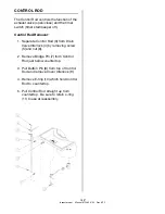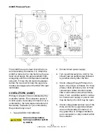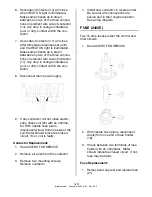
5-5
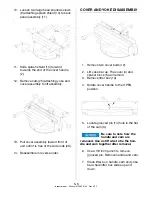
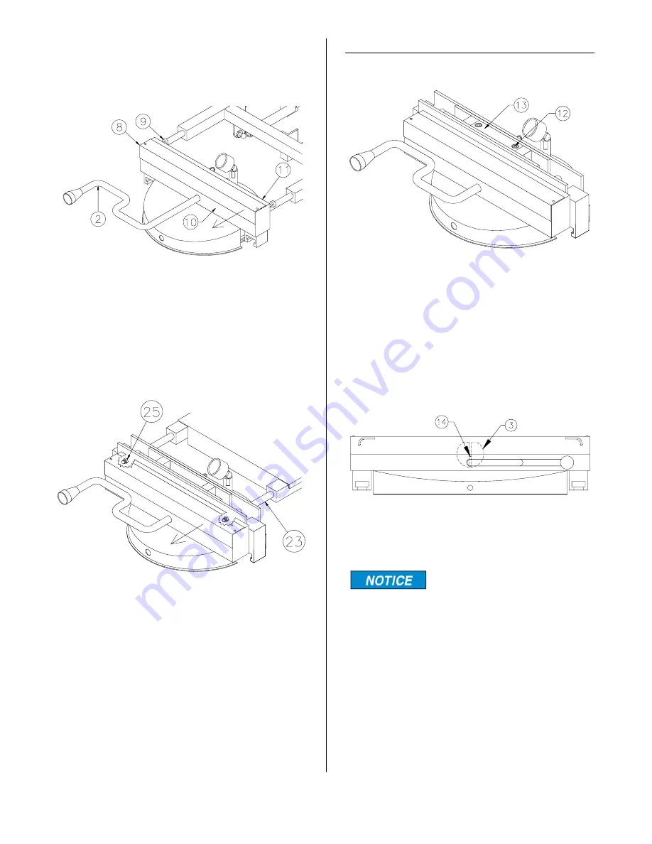
10. Loosen two large head knurled screws
(9) attaching splash shield (10) to back
panel assembly (11).
.
11. Slide splash shield (10) forward
towards the end of the cover handle
(2).
12. Remove nuts (25) attaching yoke and
cover assembly to lift assembly.
13. Pull cover assembly toward front of
unit until it is free of the slide rods (23).
14. Reassemble in reverse order.
COVER AND YOKE DISASSEMBLY
1. Remove two cover bolts (12).
2. Lift yoke bar up. The cover (4) and
spacer block (5) will remain.
3. Remove lifter box (13).
4. Rotate cover handle to the OPEN
position.
5. Locate grooved pin (14) hole in the flat
of the cam (3).
Be sure to note how the
handle and cam are
removed. Use a stiff wire to tie the han-
dle and cam together after removal.
6. Use a 1/8 inch punch to remove
grooved pin. Remove handle and cam.
7. Clean lifter box, handle, cam and yoke
bar where lifter box slides up and
down.
broaster.com Manual #15460 8/02 Rev 6/15
Summary of Contents for 2004E
Page 2: ......
Page 8: ......
Page 12: ......
Page 21: ...2 9 MODEL 2400GH DOMESTIC MODEL 2400GHXP EXPORT broaster com Manual 15460 8 02 Rev 7 14 ...
Page 22: ...2 10 MODEL 2400GHCE EU broaster com Manual 15460 8 02 Rev 7 14 1 2 2 1 2 1 ...
Page 44: ......
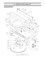
Page 45: ...5 COVER YOKE AND LIFT 5 1 FAMILIARIZATION broaster com Manual 15460 8 02 Rev 9 14 ...
Page 54: ......
Page 81: ...9 9 This page intentionally left blank broaster com Manual 15460 8 02 Rev 3 16 ...
Page 87: ...broaster com Manual 15460 8 02 SERVICE NOTES ...
Page 88: ...broaster com Manual 15460 8 02 SERVICE NOTES ...
Page 89: ...broaster com Manual 15460 8 02 SERVICE NOTES ...
Page 90: ......
Page 91: ......
Page 92: ...Broaster Company 2855 Cranston Road Beloit WI 53511 3991 608 365 0193 broaster com ...


