5-6
COVER AND YOKE ASSEMBLY
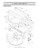
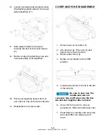
1. Install cam (3) into yoke bar.
2. Install handle (2) through splash guard,
into yoke bar then into the cam.
3. Align holes in handle and cam then
install a new grooved pin (14). Be sure
the grooved pin is installed flush with
the cam.
4. Lubricate inside of yoke bar where
lifter box slides up and down.
5. Lubricate lifter box then install lifter
box into the yoke bar.
6. Lower assembly over the cover (4) and
spacer block (5).
7. Rotate cover handle to the CLOSED
position.
8. Align holes in lifter box, spacer block
and cover.
9. Install new cover bolts but do not
tighten.
Bolts will be tightened
when centering cover at
reassembly (see Centering Cover under
ADJUSTMENTS).
CHECK CAM OPERATION
When handle is rotated, cam (3) moves
cover (4) in or out of the cooking well. Cam
and spacer block (5) lock the cover when
pressure in cooking well pushes up on the
cover.
broaster.com Manual #15460 8/02 Rev 6/15
Summary of Contents for 2004E
Page 2: ......
Page 8: ......
Page 12: ......
Page 21: ...2 9 MODEL 2400GH DOMESTIC MODEL 2400GHXP EXPORT broaster com Manual 15460 8 02 Rev 7 14 ...
Page 22: ...2 10 MODEL 2400GHCE EU broaster com Manual 15460 8 02 Rev 7 14 1 2 2 1 2 1 ...
Page 44: ......
Page 45: ...5 COVER YOKE AND LIFT 5 1 FAMILIARIZATION broaster com Manual 15460 8 02 Rev 9 14 ...
Page 54: ......
Page 81: ...9 9 This page intentionally left blank broaster com Manual 15460 8 02 Rev 3 16 ...
Page 87: ...broaster com Manual 15460 8 02 SERVICE NOTES ...
Page 88: ...broaster com Manual 15460 8 02 SERVICE NOTES ...
Page 89: ...broaster com Manual 15460 8 02 SERVICE NOTES ...
Page 90: ......
Page 91: ......
Page 92: ...Broaster Company 2855 Cranston Road Beloit WI 53511 3991 608 365 0193 broaster com ...

