6-4
Use repair kit #15279.
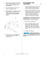
1. Remove two allen screws which attach
the valve assembly to the cooking
well.
2. Remove valve from the unit.
3. Loosen locking nut (9) then remove
valve control yoke (10) from the stem
assembly (11).
4. Remove entire stem assembly from
the housing (12) by pushing on
threaded end of the stem assembly.
5. Remove all components from the stem
assembly (11).
6. Clean then dry all metal components,
not replaced, with hot water and a mild
detergent.
7. Install new parts from the repair kit.
Lubricate all O-rings and contacting
surfaces with olive oil.
8. Mount valve assembly back on cook-
ing well with the allen screws. With
open end of yoke pointing to the left.
9. With control arm in the “CLOSED”
position, a distance of 1/16” should be
maintained between the control yoke
(10) and control rod. While locking nut
(9) is loose, adjust distance in the
pressure port located on inside top of
the cooking well. Using a screwdriver,
turn stem assembly (11) either clock-
wise or counterclockwise to obtain this
distance.
10. Tighten locking nut.
Repair:
broaster.com Manual #15460 8/02 Rev 6/15
Summary of Contents for 2004E
Page 2: ......
Page 8: ......
Page 12: ......
Page 21: ...2 9 MODEL 2400GH DOMESTIC MODEL 2400GHXP EXPORT broaster com Manual 15460 8 02 Rev 7 14 ...
Page 22: ...2 10 MODEL 2400GHCE EU broaster com Manual 15460 8 02 Rev 7 14 1 2 2 1 2 1 ...
Page 44: ......
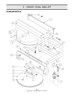
Page 45: ...5 COVER YOKE AND LIFT 5 1 FAMILIARIZATION broaster com Manual 15460 8 02 Rev 9 14 ...
Page 54: ......
Page 81: ...9 9 This page intentionally left blank broaster com Manual 15460 8 02 Rev 3 16 ...
Page 87: ...broaster com Manual 15460 8 02 SERVICE NOTES ...
Page 88: ...broaster com Manual 15460 8 02 SERVICE NOTES ...
Page 89: ...broaster com Manual 15460 8 02 SERVICE NOTES ...
Page 90: ......
Page 91: ......
Page 92: ...Broaster Company 2855 Cranston Road Beloit WI 53511 3991 608 365 0193 broaster com ...


