3.1.5 Column Support
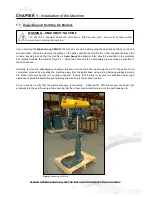
Prior to usage, ensure that the column support is securely fastened to the ground using the 3 x M16 bolt holes
provided (see Figure 2).
3.2
Preparation for Operation
The following procedure is recommended for the correct drilling using the
Brobo Group 3M Drill
.
PROCEDURE
i)
Clean the workpiece to ensure it is free of any grit, swarf or flammable substances. It is highly
recommended that a solvent be used to remove any residue, while ensuring the solvent is inflammable and
non-toxic.
ii)
Prior to drilling, clear the drill and the work area around the work piece of any swarf or/and tools to
minimise the likelihood of the user getting injured during the drilling operation.
iii)
Load the workpiece into the mechanical vice (sold separately), located on the racklift, and fastened
workpiece securely. Loosen the racklift and adjust the height and horizontal position. Once you have
position the workpiece into the desired location, relock the racklift assembly.
iv)
Check that the correct speed drill speed setting is selected, and the safety eye shield is directly positioned
to deflect swarf and any dislodged particles.
v)
Turn the machine on. Proceed by slowly drilling into the workpiece until a guide indent is created. Steadily
increase the feed rate of drilling by applying a constant yet steady force on the feed handle until the desired
hole depth is reached.
vi)
Reverse the direction of the drill fed until it come to rest in its start position and turn the drill machine off.
3.3 Operation Recommendations
To reduce the amount of frictional contact between the drill bit and work piece, a light coating of oil or
lubricant can be applied onto the drill bit price to drilling.
Do not force the drill bit through the workpiece as this significantly reduces the lifespan of the bit, as well as
increasing the risk of the bit bending and/or breaking and injuring the operator.
When drilling through larger hole diameters through thick materials, its is advisable to split the drilling
operation into two or three stages, starting from drilling a smaller hole size and increasing it until the
desired final hole size.
8
Summary of Contents for 3M
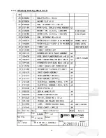
Page 12: ...CHAPTER 4 Drawings Layouts Assembly and Spare Parts 4 1 1 Assembly Drawing Sheet 1 of 5 9 ...
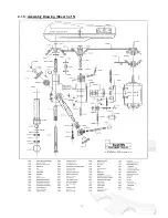
Page 13: ...4 1 2 Assembly Drawing Sheet 2 of 5 10 ...
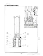
Page 14: ...4 1 3 Assembly Drawing Sheet 3 of 5 11 ...
Page 15: ...4 1 4 Assembly Drawing Sheet 4 of 5 12 ...
Page 17: ...4 2 Switch Assembly 14 ...

