


WARNING – HEAD HEAVY MACHINE
The 3M drill is heaviest where the drill head is fitted and as such, care must be taken while
relocating or moving the machine.
!
!!
!
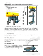
CHAPTER 1
-
Installation of the Machine
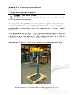
1.1 Unpacking and Handling the Machine
Upon receiving the
Brobo Group 3M Drill
, the machine should be sitting upright and bolted centrally on top of a
wooden pallet. While the machine is situated on the pallet, position the forklift arms under the pallet between the
runners, keeping in mind that the machine is
head heavy
and minimal force should be exerted on the electrical
box located beneath the machine (
Figure 1
). Move the entire unit to an accessible area as close as possible to
the final location.
Carefully remove the packaging surrounding the drill unit and the bolts restraining the drill to the pallet. Once
completed, proceed by elevating the machine away from the pallet base using a sling harness wrapped around
the entire unit ensuring that
it is
equally supported
. Ensure that the floor is as level as possible and enough
clearance is allocated before finally positioning the machine to the desired location.
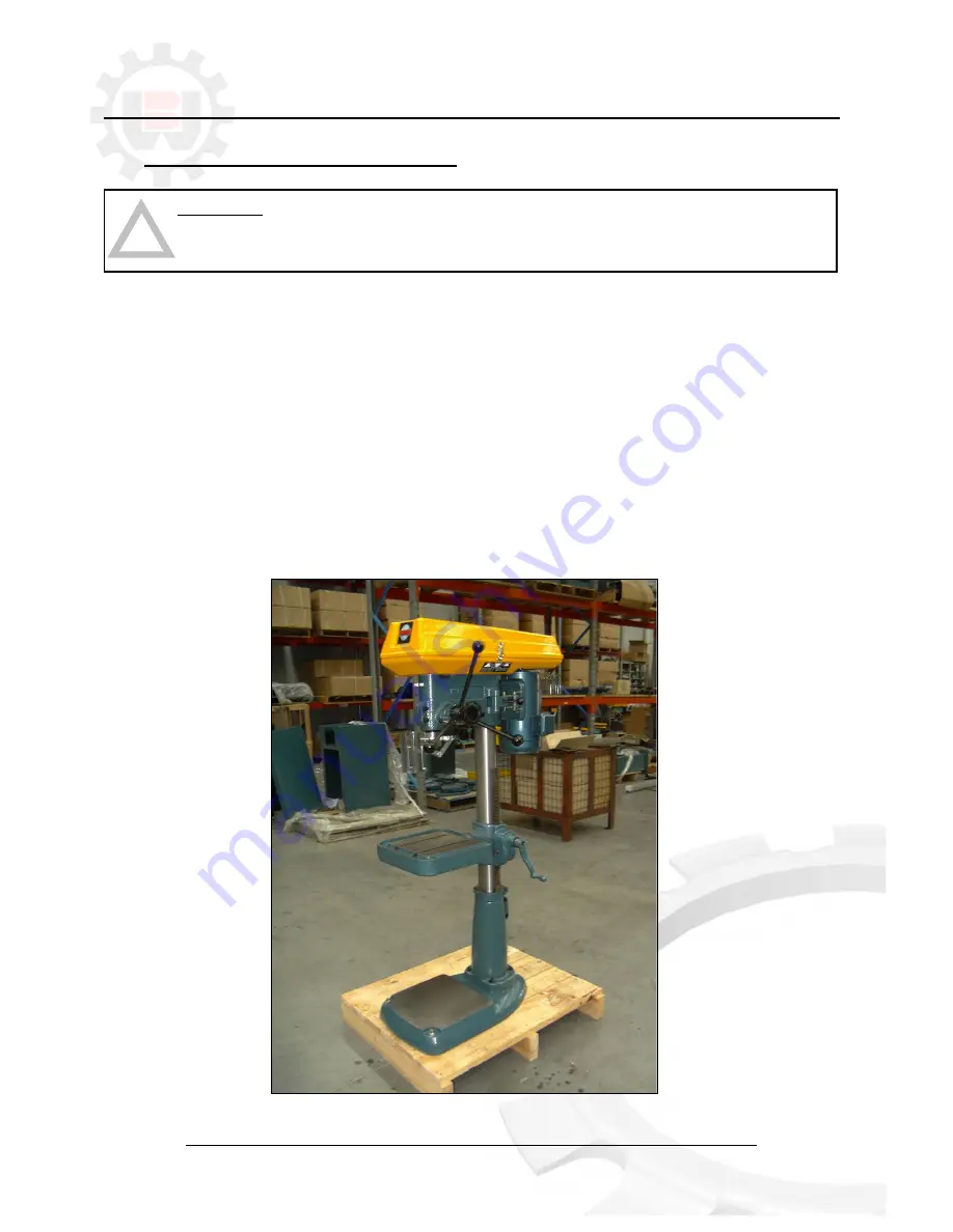
Once in position, verify that the electrical supply is connected. Attached the 3MT arbour and chuck set (not
provided) into the quill housing, while ensuring that the arbour step correctly mates into the quill housing slot.
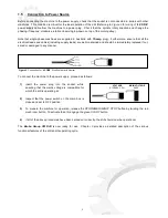
Figure 1.
Assembly of 3M Drill
PLEASE OBSERVE AND FOLLOW THE INSTALLATION INTRUCTIONS ON PAGE 2
1
Summary of Contents for 3M
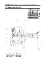
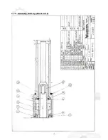
Page 12: ...CHAPTER 4 Drawings Layouts Assembly and Spare Parts 4 1 1 Assembly Drawing Sheet 1 of 5 9 ...
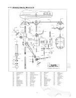
Page 13: ...4 1 2 Assembly Drawing Sheet 2 of 5 10 ...
Page 14: ...4 1 3 Assembly Drawing Sheet 3 of 5 11 ...
Page 15: ...4 1 4 Assembly Drawing Sheet 4 of 5 12 ...
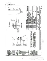
Page 17: ...4 2 Switch Assembly 14 ...


