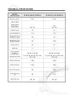
background image

    VOLTAGE 

 MAIN VOLTAGE 

415/240V 3 PH 

         240V


1.5 

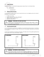
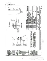
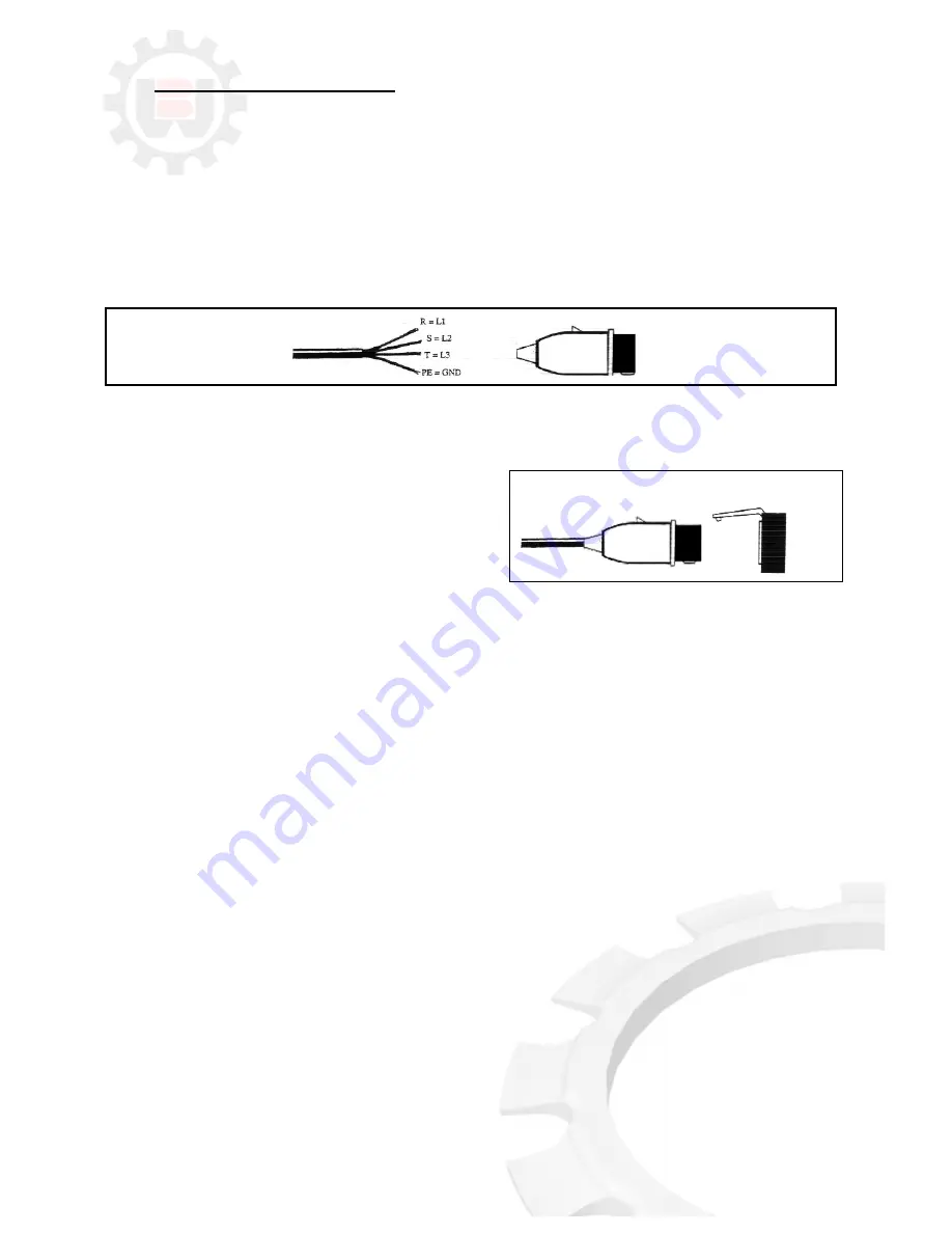
Connection to Power Source 


Before connecting the machine to the power supply, check that the socket is not connected in series with other 
machines.  This condition is critical for the ideal operation of the drill (Referring to 

Figure 3

 for wiring of “

4-CORE

” 

power supply cable from the machine to a power plug.  Check that the spindle rotary direction and change the 
phasing if required; clockwise rotation observing top-down on top of the motor pulley.)   
 
Note that single-phase machines are supplied in Australia with 

15-amp

 plug).  Furthermore, ensure that all the 

electrical leads and cables (including supply leads) are well maintained and should be immediately replaced if cut, 
sliced or damaged in any manner. 


 Figure 3

. Connection for “

4-CORE

” Wire System with Neutral


To connect the machine to the power supply, proceed as follows: 


1) 

Insert  the  power  plug  into  the  socket,  while 
ensuring  that  the  mains  voltage  is  compatible  for 
which the drill is operating at.


2) 

Inspect  that  the  power  switch  on  the  main  box  is 
closed and set to 

OFF 

position. 


3) 

To prepare the machine for operation, release the 

STOP/EMERGENCY STOP 

button by twisting the red 

mushroom button. To activate the drill, engage the green 

START

 button. 


4) 

If all of the above procedures have been carried out correctly, the drill should now be operational 

 
The 

Brobo  Group  3M  Drill

  is  now  ready  for  use.   

Chapter  3

  provides  a  detailed  description  of  the  various 

functional features of the drill and its operating cycle.   


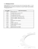
Summary of Contents for 3M

Page 1: ...PRODUCT AND MAINTENANCE MANUAL 3M PRECISION DRILLING MACHINE BROBO WALDOWN AUST PTY LTD A C N 098 264 316 A B N 42 098 264 316 65 67 Williams Rd Dandenong 3175 PO BOX 4274 Dandenong Sth 3164 Victoria AUSTRALIA Tel 61 3 9794 8751 Email info brobo com au Fax 61 3 9794 8792 Website www brobo com au Certified System Quality ISO 9001 YOUR NORTH AMERICAN BROBO DISTRIBUTOR IS ...

Page 2: ...achine 3 1 1 Drill Head Pulley Belt Assembly 7 3 1 2 Safety Eye Shields 7 3 1 3 Depth Adjustment 7 3 1 4 Racklift Assembly 7 3 1 5 Column Support 8 3 2 Preparation for Operation 8 3 3 Operation Recommendations 8 CHAPTER 4 Drawings Layouts Assembly and Spare Parts 4 1 1 Assembly Drawing 1 of 5 9 4 1 2 Assembly Drawing 2 of 5 10 4 1 3 Assembly Drawing 3 of 5 11 4 1 4 Assembly Drawing 4 of 5 12 4 1 5...

Page 3: ... 74 6 74 6 MAXIMUM DISTANCE SPINDLE TO TABLE 340 714 MAXIMUM DISTANCE SPINDLE TO BASE 530 1208 THROAT DEPTH 191 191 MOTOR kW 1 1 1 1 SPINDLE SPEEDS NOMINAL STRAIGHT DRIVE INTERMEDIATE DRIVE 480 850 1450 2500 150 280 320 480 570 650 1800 2000 3000 480 850 1450 2500 150 280 320 480 570 650 1800 2000 3000 WEIGHT UNPACKED 130kg 145kg WEIGHT PACKED 149kg 164kg HEIGHT PACKED mm 985 1390 HEIGHT INSTALLED...

Page 4: ...the entire unit to an accessible area as close as possible to the final location Carefully remove the packaging surrounding the drill unit and the bolts restraining the drill to the pallet Once completed proceed by elevating the machine away from the pallet base using a sling harness wrapped around the entire unit ensuring that it is equally supported Ensure that the floor is as level as possible ...

Page 5: ...loose are included as follows A ACCESSORIES i 1 Operation Manual 1 3 Minimum Requirements For the machine to function correctly the room in which the drill unit is to be installed must be in the vicinity of and satisfy the following conditions 415 240V Power Supply Ambient Temperature From 10 to 50 degrees C Relative Humidity Not more than 90 Lighting More than 500 LUX 1 4 Anchoring the Drill Unit...

Page 6: ...re well maintained and should be immediately replaced if cut sliced or damaged in any manner Figure 3 Connection for 4 CORE Wire System with Neutral To connect the machine to the power supply proceed as follows 1 Insert the power plug into the socket while ensuring that the mains voltage is compatible for which the drill is operating at 2 Inspect that the power switch on the main box is closed and...

Page 7: ...nt risks safety devices noise emission and accident prevention regulations provided for by national and international laws governing the use of the machine The operator must be perfectly aware of the position and functions of all the machine s controls All those concerned must strictly adhere to ALL instructions warnings and accident prevention standards in this manual The following definitions ar...

Page 8: ...y Earthing Systems The installation of the earthing system must comply with the requirements stated in the IEC Standards Part 195 Earthing and Protection Against Electric Shocks 1998 2 3 Advice for the Operator Protective eyewear or goggles must be worn at all times while attending and operating the drill Ensure that hands and arms are kept clear of the drilling zone when the machine is operating ...

Page 9: ...applicable to the Brobo Group 3M Drill are those specified by the EEC Committee that governs safety of machinery health and safety at work personal protection and safeguarding of the work environment In addition the saw also complies with the Australian Standards regarding the safeguarding and general requirements for electrical equipment 2 4 1 Reference Standards MACHINE SAFETY EEC Directive No 9...

Page 10: ...on prior to drilling to prevent any swarf dislodging in the direction of the user 3 1 3 Depth Adjustment Situated beneath the 3 pronged handle boss is the depth adjustment gauge Using the gauge and the scale indicator shown on the left hand side of the drill the operator can manually set the desired depth for a drill hole and lock its position 3 1 4 Racklift Assembly Available in round or rectangu...

Page 11: ...assembly iv Check that the correct speed drill speed setting is selected and the safety eye shield is directly positioned to deflect swarf and any dislodged particles v Turn the machine on Proceed by slowly drilling into the workpiece until a guide indent is created Steadily increase the feed rate of drilling by applying a constant yet steady force on the feed handle until the desired hole depth i...

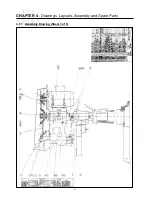
Page 12: ...CHAPTER 4 Drawings Layouts Assembly and Spare Parts 4 1 1 Assembly Drawing Sheet 1 of 5 9 ...

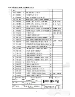
Page 13: ...4 1 2 Assembly Drawing Sheet 2 of 5 10 ...

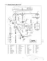
Page 14: ...4 1 3 Assembly Drawing Sheet 3 of 5 11 ...

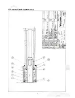
Page 15: ...4 1 4 Assembly Drawing Sheet 4 of 5 12 ...

Page 16: ...robo Group Engineering department PART NUMBER SPARE PART DESCRIPTION 1132010 BASE FLOOR TYPE 2112010 COLUMN SUPPORT use with Floor Base 2114060 COLUMN FLOOR Solid 1220mm 1035190 COLUMN BENCH Solid 767mm 2122020 COLUMN CLAMP includes 1042000 2124050 2121310 RACKLIFT ASSEMBLY COMPLETE Floor Type 1041080 RACKLIFT ASSEMBLY COMPLETE Bench Type 2114010 RACK 2111140 WORMWHEEL BUSH ASSEMBLY 2114020 WORM 2...

Page 17: ...4 2 Switch Assembly 14 ...

Page 18: ...efects 5 2 Maintenance Requirements All maintenance must be carried out with the power switched off and the machine in emergency stop condition To guarantee perfection operation all spare parts must be Brobo Group originals On completion of maintenance works ensure that the replaced parts or any tools used have been removed from the machines before starting it up Any behaviour not in accordance wi...

Page 19: ...th good quality oil v Clean the drill machine regularly and keep any unpainted surfaces lightly oiled to protect from rust and corrosion vi Ensure that the machine performs drill perpendicular to the work surface If not contact Brobo Group engineering department 16 ...

Page 20: ...rill hole Ensure that the vice clamps is securely fastened to the work piece prior to drilling Slow down the drill feed rate else it might cause the drill bit to break and cause harm to the operator Check that no swarf is lodged in the chuck unit Remove aggregate using an air gun Also check that the chuck teeth are not worn If so the chuck unit might need to be replaced Please ensure that the work...

Page 21: ...ents can be purchase direct from your nearest Brobo distributor For more information please check www brobo com au All component to the 3M drill are sold as spare parts pending availability Please contact your nearest Brobo distributor or our Brobo Group head office Please visit www brobo com au for more details 18 ...

Page 22: ... isolated prior to opening electrical enclosures Noise Low Under no load testing the noise level measured is below 80db A If the noise level becomes too high during a drilling cycle stop the process and inspect for problem if any are present Substance Low Keep the work area clean and regularly remove excess coolant oils and other aggregate Hazardous Events Unexpected Start Up Low During a power fa...

Page 23: ... normal wear and tear on the goods 1 5 The Supplier is under no obligation under this warranty where the Customer has failed to observe the terms of payment for the goods or any other obligation imposed by the terms and conditions of this warranty 1 6 In the event that the Supplier is supplying goods which have been manufactured by third parties the Customer shall be entitled to the benefit of any...

Reviews: