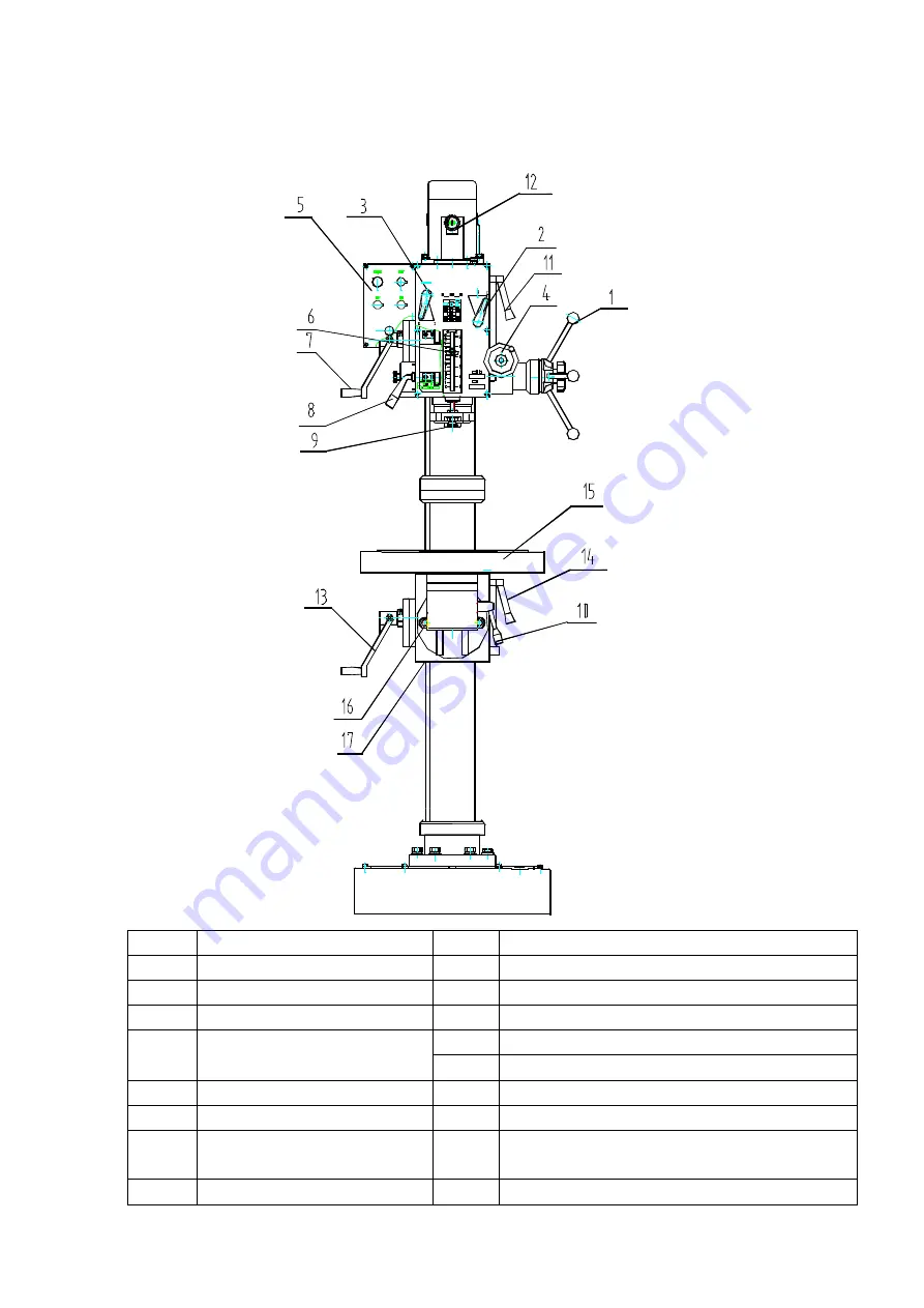
8. Main Functions and Operation of the Machine
No
Name
No
Name
1
Feed handle of spindle
9
Depth setting nut
2
Speed change handle
10
Lock handle of working-table
3
Speed change handle
11
Lock handle of headstock
4
Micro feed handle
12
Tool retracting handle
13
Up and down handle of supporting block
5
Control panel of electric
14
Lock handle of supporting block
6
Block of Scale orientation
15
Working table
7
Up and down handle of
Headstock
16
Lock nut
8
Lock handle of spindle
17
Supporting table
BDF 32-1
Summary of Contents for BDF32-1
Page 6: ...1 Outline Drawing Figure 1 BDF 32 1 ...
Page 9: ...Figure 2 Drawing of Transmission System ...
Page 11: ......
Page 14: ...Figure 7 Installation of Foundation ...
Page 17: ...9 Assembly Drawings Spare Parts List ...
Page 18: ......
Page 21: ......
Page 27: ......