background image

38

Brocade TurboIron 24X Series Hardware Installation Guide

Part Number: 53-1003053-03

Connecting Network Devices and Checking Connectivity

Troubleshooting network connections


Troubleshooting network connections

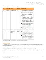
For the indicated port, verify that both ends of the cabling (at the TurboIron device and the connected device) are snug.

Verify that the TurboIron device and the connected device are both powered on and operating correctly.

Verify that you have used the correct cable type for the connection:

For twisted-pair connections to an end node, use straight-through cabling.

For fiber-optic connections, verify that the transmit port on the device is connected to the receive port on the connected 
device, and that the receive port on the device is connected to the transmit port on the connected device.

Verify that the port has not been disabled through a configuration change. You can use the CLI. If you have configured an IP 
address on the device, you also can use 

Brocade Network Advisor

.

For copper ports, you can test the cable using Virtual Cable Testing (VCT). Refer to "Monitoring Hardware Components" in the 

TurboIron Configuration Guide

.

If the other procedures don't resolve the problem, try using a different port or a different cable.

Support for digital optical monitoring

You can configure your TurboIron device to monitor optical transceivers in the system, either globally or by specified port. When this 
feature is enabled, the system monitors the temperature and signal power levels for the optical transceivers in the specified ports. Console 
messages and syslog messages are sent when optical operating conditions fall below or rise above the SFP+ or SFP manufacturer 
recommended thresholds. For more information about digital optical monitoring, refer to the 

TurboIron Configuration Guide

.

Summary of Contents for Brocade TurboIron 24 Series

Page 1: ...Part Number 53 1003053 03 Publication Date 15 June 2017 Brocade TurboIron 24X Series Hardware Installation Guide HARDWARE INSTALLATION GUIDE...

Page 2: ...e This informational document describes features that may not be currently available Contact a Brocade sales office for information on feature and product availability Export of technical data contain...

Page 3: ...and power supplies 16 Power supplies 17 Installing the TurboIron 24X Unpacking a system 19 Package contents 19 General requirements 19 Summary of installation tasks 20 Installation precautions 20 Gene...

Page 4: ...ges 40 Changing the temperature warning level 40 Changing the device temperature polling interval 40 Removing MAC address entries 41 Maintaining the TurboIron 24X Hardware Hardware maintenance schedul...

Page 5: ...ut connector and plug 62 Regulatory compliance 63 Safety warnings 63 Electrical specifications 64 Regulatory Approval and Statements Agency approvals 65 Safety agency approvals 65 Electromagnetic emis...

Page 6: ...6 Brocade TurboIron 24X Series Hardware Installation Guide Part Number 53 1003053 03...

Page 7: ...tax components Delimiters and operators define groupings of parameters and their logical relationships Format Description bold text Identifies command names Identifies keywords and operands Identifies...

Page 8: ...to the minute information on Brocade products and resources go to MyBrocade You can register at no cost to obtain a user ID and password Release notes are available on MyBrocade under Product Downloa...

Page 9: ...OEM For questions regarding service levels and response times contact your OEM Solution Provider Document feedback To send feedback and report errors in the documentation you can use the feedback for...

Page 10: ...10 Brocade TurboIron 24X Series Hardware Installation Guide Part Number 53 1003053 03 Preface Document feedback...

Page 11: ...cade TurboIron 24X Series Hardware Installation Guide 11 Part Number 53 1003053 03 About this Document What s new in this document 11 What s new in this document There is no enhancements in this editi...

Page 12: ...12 Brocade TurboIron 24X Series Hardware Installation Guide Part Number 53 1003053 03 About this Document What s new in this document...

Page 13: ...and video applications for converged services The TurboIron 24X supports Twenty four SFP ports at either 1 GbE or 10 GbE using the standard E1MG optics as well as the new SFP 10GbE optics Four 10 100...

Page 14: ...labeled Console enables you to configure and manage the device using a third party terminal emulation application on a directly connected PC straight through EIA or TIA DB 9 serial cable M F is inclu...

Page 15: ...n 1 Part PLRXPLSCS4371 Serial xxxxxxxxx Port 7 Type 10G XG SR SFP Vendor Brocade Version 1 Part PLRXPLSCS4371 Serial xxxxxxxxx Port 8 Type EMPTY Port 9 Type EMPTY Port 10 Type EMPTY Port 11 Type EMPTY...

Page 16: ...nd of the link and adjust port speed accordingly 10 100 1000 ports on the TurboIron 24X support RJ 45 copper connectors The output of the show media command displays C next to the ports that have copp...

Page 17: ...pper port connection exists or the link is down Act This is the right LED on RJ45 On or Blinking Traffic is being transmitted or received on the copper port Off No traffic is being transmitted or rece...

Page 18: ...one of the supplies without interrupting operation because the remaining power supply provides enough power for all of the ports For power supply hardware specifications refer to Power supply specific...

Page 19: ...the contents If any items are missing please contact the place of purchase Package contents Verify the package contents listed below Brocade TurboIron 24X device with dual AC power supplies installed...

Page 20: ...to the regulatory requirements outlined in this manual Powering on the system on page 27 4 Verify that power LED is on after the system is powered on Verifying proper operation on page 27 5 Attach a t...

Page 21: ...e the running configuration to the startupconfig file Changes or modifications made to this device that are not expressly approved by the party responsible for compliance could void the user s authori...

Page 22: ...ou insert the power supply right side up It is possible to insert the supply upside down although the supply will not engage with the power backplane cotter pin when plugged upside down The label of t...

Page 23: ...while a power supply is being installed or removed but the power supply itself should not be connected to a power source Otherwise you could be injured or the power supply or other parts of the devic...

Page 24: ...g over Mount devices in a rack or cabinet as low as possible Place the heaviest device at the bottom and progressively lighter devices above Desktop installation Follow the steps for desktop installat...

Page 25: ...e manufacturer Reduced Air Flow Installation of the equipment in a rack should be such that the amount of air flow required for safe operation of the equipment is not compromised Circuit Overloading C...

Page 26: ...ttach the other bracket to the other side Make sure you use the screws supplied with the mounting brackets Using the wrong screws could damage the TurboIron 24X and would invalidate your warranty Figu...

Page 27: ...l power supplies are fully and properly inserted Remove the power cord from the shipping package Attach the AC power cord to the AC connector on the rear panel as shown in Figure 3 NOTE Align the loca...

Page 28: ...ctions You will need to assign an IP address using the CLI You can access the CLI by attaching management station through a serial cable to the Console port After you assign an IP address you can acce...

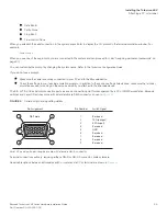
Page 29: ...the settings in your terminal emulation program In addition to the session settings listed above make sure the terminal emulation session is running on the same serial port you attached to the Brocad...

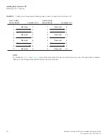
Page 30: ...r PC NOTE As indicated in Figure 4 and Figure 5 some of the wires should not be connected If you do connect the wires that are labeled Reserved you might get unexpected results with some terminals 1 2...

Page 31: ...t a CLI session At this level you can view some system information but you cannot configure system or port parameters Privileged EXEC Also called the Enable level and can be secured by a password At t...

Page 32: ...not require passwords However if someone has configured a password for the device but the password has been lost you can regain Super User access to the device using the following procedure NOTE Recov...

Page 33: ...the following command at the Privileged EXEC level prompt for example TurboIron Switch then press Enter This command erases the factory test configuration if still present TurboIron erase startup con...

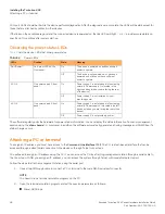
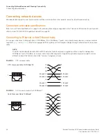
Page 34: ...10 100Base TX or 1000Base T switch or another Brocade device a crossover cable is required Figure 1 and Figure 2 If the hub is equipped with an uplink port it will require a straight through cable in...

Page 35: ...ormation about this feature and how configure it refer to the TurboIron Configuration Guide Connecting a network device to a fiber port For direct attachment from the Brocade device to a Gigabit NIC s...

Page 36: ...them In particular dust can accumulate in the connectors and cause problems such as reducing the optic launch power To clean the fiber cable connectors Brocade recommends that you use the fiber optic...

Page 37: ...tion to the other network device has been properly made Also make certain that the other network device is powered on and operating correctly Verify that the transmit port on the Brocade device is con...

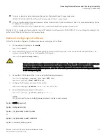
Page 38: ...vice Verify that the port has not been disabled through a configuration change You can use the CLI If you have configured an IP address on the device you also can use Brocade Network Advisor For coppe...

Page 39: ...rature sensors according to the device poll time which is 60 seconds by default If the temperature equals or exceeds the warning temperature the software generates a Syslog message and SNMP trap You c...

Page 40: ...perature 50 0 C degrees warning level 45 0 C degrees Changing the temperature warning level The default warning temperature is 45 0 C degrees You can change the warning temperature using the temperatu...

Page 41: ...or example to remove entries for the MAC address 00 00 00 in all VLANs enter the following command at the Privileged EXEC level of the CLI TurboIron clear mac address 00 00 00 Syntax clear mac address...

Page 42: ...42 Brocade TurboIron 24X Series Hardware Installation Guide Part Number 53 1003053 03 Managing the TurboIron 24X Removing MAC address entries...

Page 43: ...fiber optic connectors on fiber optic ports and the connected fiber cable each time you disconnect the cable You can replace the following hardware components as needed Fiber optic modules SFP transc...

Page 44: ...dule out of the port by pulling the latch forward away from the front panel of the module as shown in Figure 1 This unlocks the module from the front panel On 1000BaseSX ports the latch is enclosed in...

Page 45: ...ors a tab on each connector should face upward into the port connector or connectors until the tabs lock into place 4 Observe the link and active LEDs to determine if the network connections are funct...

Page 46: ...device in an environment where the operating ambient temperature might exceed 40 C 104 F Never leave tools inside the device Determining which power supply failed If you are replacing a power supply t...

Page 47: ...se procedures Figure 3 shows a front view of the AC power supply FIGURE 3 AC power supply Removing an AC power supply Follow the steps to remove an AC power supply 1 Unplug the power cord from the pow...

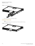
Page 48: ...TurboIron 24X Hardware Replacing a power supply FIGURE 5 Removing the power supply 6 Place the power supply in an anti static bag for storage Installing an AC power supply NOTE If the empty power supp...

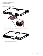
Page 49: ...ectly aligned With the other hand support the underside of the power supply and insert the power supply into the empty power supply slot 3 Push inward until the supply is completely in the slot so tha...

Page 50: ...Maintaining the TurboIron 24X Hardware Replacing a power supply FIGURE 8 Installing the power supply 4 Lock the power supply in place by securing the two captive screws as shown in Figure 9 FIGURE 9...

Page 51: ...ed on and running The fan tray is located in a slot at the rear of the TurboIron 24X This section provides information about the following topics Installation precautions and warnings Replacing the fa...

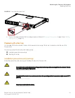
Page 52: ...boIron 24X fan tray location 1 Disconnect the power cord from the power supply 2 Loosen the two captive screws on the front plate of the fan tray and slide the tray out of the device as shown in Figur...

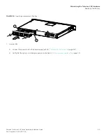
Page 53: ...e TurboIron 24X Hardware Replacing the fan tray FIGURE 13 Inserting a replacement fan tray 5 Connect the power cord to the power supply refer to Powering on the system on page 18 6 Verify that the sys...

Page 54: ...54 Brocade TurboIron 24X Series Hardware Installation Guide Part Number 53 1003053 03 Maintaining the TurboIron 24X Hardware Replacing the fan tray...

Page 55: ...ions Cooling Regulatory compliance Power source interruptions Mean time between failure Pinouts and signalling Cable specifications Power cords Power supply specifications Overview Key features Physic...

Page 56: ...uration to intake air from the front left and right sides through the device and then expel it at the rear of the device as shown in Figure 1 TABLE 1 Physical dimensions and weight of the TurboIron 24...

Page 57: ...mmunity standards and safety agency approvals for TurboIron 24X switches Power source interruptions Table 5 shows how the TurboIron 24X protects against power surges and power drops 1 Left intake 3 Ri...

Page 58: ...signalling details Most PC serial ports also require a cable with a female DB 9 connector Terminal connections will vary requiring either a DB 9 or DB 25 connector male or female Serial cable options...

Page 59: ...cable specifications for the cables used with the Gigabit and 10 Gigabit Ethernet ports NOTE Cable installation and network configuration will affect overall transmission capability The numbers provid...

Page 60: ...310 nm 2 10000 10 km 1000Base LHA SMF LC connector for SFP module 9 1550 nm 2 70000 70 km 1000Base LHB SMF LC connector for SFP module 9 1550 nm 2 120000 120 km 1000Base LX Multi mode Fiber MMF LC con...

Page 61: ...power supply The power supplies can be swapped in or out of the device while the device is running without opening the device You can remove one of the power supplies without interrupting operation T...

Page 62: ...ower supplies TABLE 9 Operating environmental conditions for power supplies Description Range Operating temperature 0 40 C 32 104 F Fan inlet temperature 43 45 C 109 4 113 F Fan vent temperature 52 53...

Page 63: ...an electrical hazard label and with the safety warnings shown in Table 13 No operator serviceable parts inside Refer servicing to qualified personnel TABLE 12 Power supply regulatory compliance Descr...

Page 64: ...ONE Non aprire Rivolgersi a personale qualificado CUIDADO Partes adentro no reparables por el operador Refiera reparo a personal autorizado ATTENTION Entretien et r partions internes ne sont autoris s...

Page 65: ...Optical Fibre Communication Systems Electromagnetic emission ICES 003 Electromagnetic Emission FCC Class A EN 55022 or CISPR 22 Class A or VCCI Class A AS or ZS 55022 EN 61000 3 2 Power Line Harmonics...

Page 66: ...se the user will be required to correct the interference at his own expense Changes or modifications made to this device which are not expressly approved by TurboIron could void the user s authority t...

Page 67: ...nslation of above statement ATTENTION Never use the power cord packed with your equipment for other products Korea English translation of above statement Class A device Broadcasting Communication Devi...

Page 68: ...ab yungh youq gij digih haijbaz 2000m doxroengz haenx ancienz sawjyungh English translation disconnect all power sources before service For non tropical use For altitude 2000 meter and below China CCC...

Page 69: ...ents BSMI statement Taiwan English translation of above statement Warning This is a class A product In a domestic environment this product may cause radio interference in which case the user may be re...

Page 70: ...70 Brocade TurboIron 24X Series Hardware Installation Guide Part Number 53 1003053 03 Regulatory Approval and Statements Regulatory statements...

Page 71: ...emove the power cord from a power supply before you install it in or remove it from the device Otherwise the power supply or the device could be damaged as a result The device can be running while a p...

Page 72: ...ce Compare this total with the rating limit for the circuit The maximum ampere ratings are usually printed on the devices near the input power connectors VORSICHT Stromkreise Verdrahtung und berlastsc...

Page 73: ...ite memory escribir memoria para guardar la configuraci n en ejecuci n en el archivo startupconfig CAUTION Never leave tools inside the chassis VORSICHT Lassen Sie keine Werkzeuge im Chassis zur ck MI...

Page 74: ...es conform ment des indications du fabricant PRECAUCI N Peligro de explosi n si la bater a se sustituye incorrectamente Sustituya solamente por el mismo o tipo equivalente recomendado por el fabricant...

Page 75: ...e de corriente DANGER If the installation requires a different power cord than the one supplied with the device make sure you use a power cord displaying the mark of the safety agency that defines the...

Page 76: ...ez d tre bless ou le bloc d alimentation ou d autres pi ces du dispositif risquent d tre endommag s PELIGRO Los suministros de corriente pueden intercambiarse sin necesidad de ajustes No obstante Broc...

Page 77: ...das Ventilatorblech gesteckt werden wenn dieses vom Geh use abgenommen wird Der Ventilator kann sich unter Umst nden noch mit hoher Geschwindigkeit drehen DANGER Faites attention de ne pas accidentel...

Page 78: ...78 Brocade TurboIron 24X Series Hardware Installation Guide Part Number 53 1003053 03 Caution and Danger Notices Danger...

Reviews: