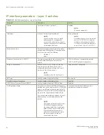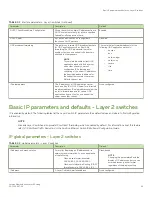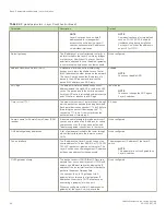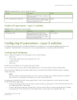
NOTE
If you set the MTU of a port to a value lower than the global MTU and from 576 through 1499, the port fragments the packets.
However, if the port MTU is exactly 1500 and this is larger than the global MTU, the port drops the packets. For ICX 7250, ICX
7450, and ICX 7750 devices, the minimum IPv4 and IPv6 MTU values for both physical and virtual interfaces are 1280.
NOTE
You must save the configuration change and then reload the software to enable jumbo
support.
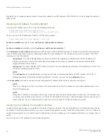
To change the MTU for interface 1/1/5 to 1000, enter the following commands.
device(config)# interface ethernet 1/1/5
device(config-if-1/1/5)# ip mtu 1000
device(config-if-1/1/5)# write memory
device(config-if-1/1/5)# end
device# reload
Syntax:
[no] ip mtu
num
The
num
variable specifies the MTU. Ethernet II packets can hold IP packets from 576 through 1500 bytes long. If jumbo mode is
enabled, Ethernet II packets can hold IP packets up to 10,218 bytes long. Ethernet SNAP packets can hold IP packets from 576
through 1492 bytes long. If jumbo mode is enabled, SNAP packets can hold IP packets up to 10,214 bytes long. The default MTU for
Ethernet II packets is 1500. The default MTU for SNAP packets is 1492.
Path MTU discovery (RFC 1191) support
FastIron X Series devices support the path MTU discovery method described in RFC 1191. When the Brocade device receives an IP
packet that has its Do not Fragment (DF) bit set, and the packet size is greater than the MTU value of the outbound interface, then the
Brocade device returns an ICMP Destination Unreachable message to the source of the packet, with the Code indicating "fragmentation
needed and DF set". The ICMP Destination Unreachable message includes the MTU of the outbound interface. The source host can use
this information to help determine the maximum MTU of a path to a destination.
RFC 1191 is supported on all interfaces.
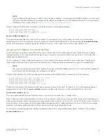
Changing the router ID
In most configurations, a Layer 3 switch has multiple IP addresses, usually configured on different interfaces. As a result, a Layer 3 switch
identity to other devices varies depending on the interface to which the other device is attached. Some routing protocols, including Open
Shortest Path First (OSPF) and Border Gateway Protocol version 4 (BGP4), identify a Layer 3 switch by just one of the IP addresses
configured on the Layer 3 switch, regardless of the interfaces that connect the Layer 3 switches. This IP address is the router ID.
NOTE
Routing Information Protocol (RIP) does not use the router ID.
NOTE
If you change the router ID, all current BGP4 sessions are cleared.
By default, the router ID on a Brocade Layer 3 switch is one of the following:
•
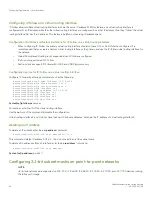
If the router has loopback interfaces, the default router ID is the IP address configured on the lowest numbered loopback
interface configured on the Layer 3 switch. For example, if you configure loopback interfaces 1, 2, and 3 as follows, the default
router ID is 10.9.9.9/24:
–
Loopback interface 1, 10.9.9.9/24
–
Loopback interface 2, 10.4.4.4/24
Configuring IP parameters - Layer 3 switches
FastIron Ethernet Switch Layer 3 Routing
48
53-1003627-04
Summary of Contents for FastIron SX 1600
Page 2: ...FastIron Ethernet Switch Layer 3 Routing 2 53 1003627 04 ...
Page 16: ...FastIron Ethernet Switch Layer 3 Routing 16 53 1003627 04 ...
Page 20: ...FastIron Ethernet Switch Layer 3 Routing 20 53 1003627 04 ...
Page 142: ...FastIron Ethernet Switch Layer 3 Routing 142 53 1003627 04 ...
Page 150: ...FastIron Ethernet Switch Layer 3 Routing 150 53 1003627 04 ...
Page 200: ...FastIron Ethernet Switch Layer 3 Routing 200 53 1003627 04 ...
Page 214: ...FastIron Ethernet Switch Layer 3 Routing 214 53 1003627 04 ...
Page 350: ...FastIron Ethernet Switch Layer 3 Routing 350 53 1003627 04 ...
Page 476: ...FastIron Ethernet Switch Layer 3 Routing 476 53 1003627 04 ...
Page 588: ...FastIron Ethernet Switch Layer 3 Routing 588 53 1003627 04 ...

