The Backup routers wait for a period of time called the dead interval for a Hello message from the Master. If a Backup router does not
receive a Hello message by the time the dead interval expires, the Backup router assumes that the Master router is dead and negotiates
with the other Backup routers to select a new Master router. The Backup router with the highest priority becomes the new Master.
Master and Owner backup routers
If the Owner becomes unavailable, but then comes back online, the Owner again becomes the Master router. The Owner becomes the
Master router again because it has the highest priority. The Owner always becomes the Master again when the Owner comes back
online.
NOTE
If you configure a track port on the Owner and the track port is down, the Owner priority is changed to the track priority. In this
case, the Owner does not have a higher priority than the Backup router that is acting as the Master router and the Owner
therefore does not resume its position as the Master router.
By default, if a Backup is acting as the Master, and the original Master is still unavailable, another Backup can "preempt" the Backup that
is acting as the Master. This can occur if the new Backup router has a higher priority than the Backup router that is acting as the Master.
You can disable this behavior. When you disable preemption, a Backup router that has a higher priority than the router that is currently
acting as the Master does not preempt the new Master by initiating a new Master negotiation.
NOTE
Regardless of the setting for the preempt parameter, the Owner always becomes the Master again when it comes back online.
Track ports and track priority
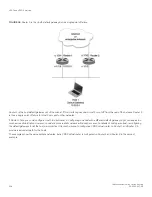
The Brocade implementation of VRRP enhances the protocol by giving a VRRP router the capability to monitor the state of the
interfaces on the other end of the route path through the router. For example, in
on page 507, interface e1/1/6 on
Switch 1 owns the IP address to which Host1 directs route traffic on its default gateway. The exit path for this traffic is through the Switch
1 e1/2/4 interface.
Suppose interface e1/2/4 goes down. Even if interface e1/1/6 is still up, Host1 is cut off from other networks. In conventional VRRP,
Switch 1 would continue to be the Master router despite the unavailability of the exit interface for the path the router is supporting.
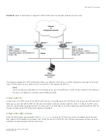
However, if you configure interface e1/1/6 to track the state of interface e1/2/4, if e1/2/4 goes down, interface e1/1/6 responds by
changing the Switch 1 VRRP priority to the value of the track priority. In the configuration shown in
on page 507, the
Switch 1 priority changes from 255 to 20. One of the parameters contained in the Hello messages the Master router sends to its
Backup routers is the Master router priority. If the track port feature results in a change in the Master router priority, the Backup routers
quickly become aware of the change and initiate a negotiation to become the Master router.
In
on page 507, the track priority results in the Switch 1 VRRP priority becoming lower than the Switch 2 VRRP priority.
As a result, when Switch 2 learns that it now has a higher priority than Switch 1, Switch 2 initiates negotiation to become the Master
router and becomes the new Master router, thus providing an open path for the Host1 traffic. To take advantage of the track port feature,
make sure the track priorities are always lower than the VRRP priorities. The default track priority for the router that owns the VRID IP
addresses is 2. The default track priority for Backup routers is 1. If you change the track port priorities, make sure you assign a higher
track priority to the Owner of the IP addresses than the track priority you assign on the Backup routers.
VRRP and VRRP-E overview
FastIron Ethernet Switch Layer 3 Routing
53-1003627-04
511
Summary of Contents for FastIron SX 1600
Page 2: ...FastIron Ethernet Switch Layer 3 Routing 2 53 1003627 04 ...
Page 16: ...FastIron Ethernet Switch Layer 3 Routing 16 53 1003627 04 ...
Page 20: ...FastIron Ethernet Switch Layer 3 Routing 20 53 1003627 04 ...
Page 142: ...FastIron Ethernet Switch Layer 3 Routing 142 53 1003627 04 ...
Page 150: ...FastIron Ethernet Switch Layer 3 Routing 150 53 1003627 04 ...
Page 200: ...FastIron Ethernet Switch Layer 3 Routing 200 53 1003627 04 ...
Page 214: ...FastIron Ethernet Switch Layer 3 Routing 214 53 1003627 04 ...
Page 350: ...FastIron Ethernet Switch Layer 3 Routing 350 53 1003627 04 ...
Page 476: ...FastIron Ethernet Switch Layer 3 Routing 476 53 1003627 04 ...
Page 588: ...FastIron Ethernet Switch Layer 3 Routing 588 53 1003627 04 ...

