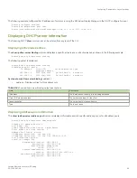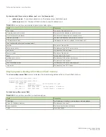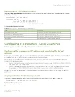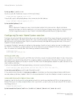
Displaying summary DHCP server information
The
show ip dhcp-server summary
command displays information about active leases, deployed address-pools, undeployed address-
pools, and server uptime.
device# show ip dhcp-server summary
DHCP Server Summary:
Total number of active leases: 2
Total number of deployed address-pools: 1
Total number of undeployed address-pools: 0
Server uptime: 0d:0h:8m:27s
Syntax:
show ip dhcp-server summary
TABLE 15
show ip dhcp-server summary output descriptions
Field
Description
Total number of active leases
Indicates the number of leases that are currently active
Total number of deployed address-pools
The number of address pools currently in use.
Total number of undeployed address-pools
The number of address-pools being held in reserve.
Server uptime
The amount of time that the server has been active.
Configuring IP parameters - Layer 2 switches
The following sections describe how to configure IP parameters on a Brocade Layer 2 switch.
Configuring the management IP address and specifying the default
gateway
To manage a Layer 2 switch using Telnet or Secure Shell (SSH) CLI connections or the Web Management Interface, you must configure
an IP address for the Layer 2 switch. Optionally, you also can specify the default gateway.
Brocade devices support both classical IP network masks (Class A, B, and C subnet masks, and so on) and Classless Interdomain
Routing (CIDR) network prefix masks:
•
To enter a classical network mask, enter the mask in IP address format. For example, enter "10.157.22.99 255.255.255.0" for
an IP address with a Class-C subnet mask.
•
To enter a prefix network mask, enter a forward slash ( / ) and the number of bits in the mask immediately after the IP address.
For example, enter "10.157.22.99/24" for an IP address that has a network mask with 24 significant bits (ones).
By default, the CLI displays network masks in classical IP address format (example: 255.255.255.0). You can change the display to
prefix format.
Assigning an IP address to a Brocade Layer 2 switch
To assign an IP address to a Brocade Layer 2 switch, enter a command such as the following at the global CONFIG level.
device(config)# ip address 10.45.6.110 255.255.255.0
Syntax:
ip address
ip-add rip-mask
or
Configuring IP parameters - Layer 2 switches
FastIron Ethernet Switch Layer 3 Routing
53-1003627-04
95
Summary of Contents for FastIron SX 1600
Page 2: ...FastIron Ethernet Switch Layer 3 Routing 2 53 1003627 04 ...
Page 16: ...FastIron Ethernet Switch Layer 3 Routing 16 53 1003627 04 ...
Page 20: ...FastIron Ethernet Switch Layer 3 Routing 20 53 1003627 04 ...
Page 142: ...FastIron Ethernet Switch Layer 3 Routing 142 53 1003627 04 ...
Page 150: ...FastIron Ethernet Switch Layer 3 Routing 150 53 1003627 04 ...
Page 200: ...FastIron Ethernet Switch Layer 3 Routing 200 53 1003627 04 ...
Page 214: ...FastIron Ethernet Switch Layer 3 Routing 214 53 1003627 04 ...
Page 350: ...FastIron Ethernet Switch Layer 3 Routing 350 53 1003627 04 ...
Page 476: ...FastIron Ethernet Switch Layer 3 Routing 476 53 1003627 04 ...
Page 588: ...FastIron Ethernet Switch Layer 3 Routing 588 53 1003627 04 ...

