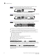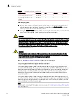
26
Brocade FastIron X Series Chassis Hardware Installation Guide
53-1001723-02
Hardware features
1
NOTE
The POE LEDs work only when POE is enabled on your device.
LEDs for 24-port copper module
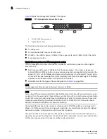
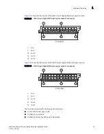
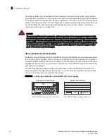
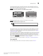
The front panel of the 24-port Gigabit Ethernet copper module includes 24 LEDs that indicate the
status of each port, and 24 LEDs (on bottom) that indicate the status of POE.
NOTE
The POE LEDs work only when POE is enabled on your device.
The copper ports provide status information using the LEDs described in
24-port Gigabit Ethernet fiber interface module
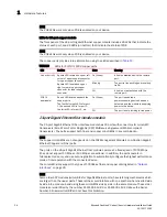
The 24-port Gigabit Ethernet Fiber interface module has 24 ports with connectors for mini-GBIC
transceivers (Small Form Factor Pluggable (SFP) Multisource Agreement (MSA)-compliant
transceivers). The ports support both fiber and copper mini-GBICs in any combination.
NOTE
The copper mini-GBICs are not supported on the FSX Management Module’s combination Gigabit
Ethernet Copper and Fiber ports.
The ports on the 24-port Gigabit Ethernet fiber module operate at a fixed speed of 1000 Mbps
(they do not support 10 Mbps or 100 Mbps connections). In addition, the ports operate in
full-duplex mode only, and use auto-negotiation to automatically configure the highest performance
mode of inter-operation with the connected device.
The mini-GBIC slots support the types of 1000Base fiber and copper cabling listed in
NOTE
Some older SFP modules (mini-GBICs for Gigabit Ethernet ports) have latching mechanisms which
are larger than the newer parts. These latches could interfere with one another when inserted side
by side into a module. Avoid using these mini-GBICs side by side in the same module. These older
modules are identified by the number PL-XPL-00-S13-22 or PL-XPL-00-L13-23 above the Serial
Number. All newer mini-GBICs do not have this limitation.
TABLE 10
LEDs for 10/100/1000 copper ports
LED
Position
State
Meaning
Link or Activity
Square LED located on upper left
corner of upper copper connector
for upper copper connector
Square LED located on upper
right corner of upper copper
connector for lower copper
connector
On (Green)
A link is established with the remote
port.
Blinking
The port is transmitting and receiving
traffic.
Off
A link is not established with the
remote port.
POE (if
applicable)
Round LED located beneath the
copper ports
The first (left-most) LED is for port
1, the second LED is for port 2,
the third LED is for port 3, etc.
On (Green)
The port is enabled, a
power-consuming device has been
detected, and the module is supplying
power to the device.
Off
The port is not providing in-line power.

