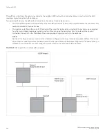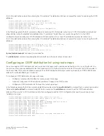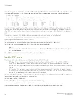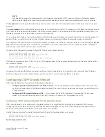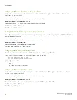
reason, the NSR-capable router waits for LSA synchronization of the standby module to complete (Sync-Ack) and then acknowledges
the neighbor that sent the LSA.
LSA syncing and packing
When the LSA processing is completed on the active management module and the decision is made to install the LSA in its link state
database (LSDB), OSPF synchronizes that LSA to the standby module. OSPF checks the current state of the database entry whether or
not it is marked for deletion. After checking the database state, OSPF packs the LSA status and other necessary information needed for
direct installation in the standby OSPF LSDB along with the LSA portion. When the LSA reaches the standby module, OSPF checks the
database entry state in the buffer and takes appropriate action, such as adding, overwriting, updating, or deleting the LSA from the LSDB.
Neighbor router synchronization
When the neighbor router is added in the active management module, it is synchronized and added to the standby module. When the
neighbor is deleted in the active module, it is synchronized to the standby and deleted in the standby. When the neighbor router state
becomes 2WAY or FULL, the neighbor router is synchronized to the standby module.The following attributes of the neighbor router is
synchronized to the standby module:
•
Neighbor router id
•
Neighbor router ip address
•
Destination router or backup destination router information
•
Neighbor state 2WAY or FULL
•
MD5 information
•
Neighbor priority
Limitations
•
If a neighbor router is inactive for 30 seconds, and if the standby module takes over in another 10 seconds, the neighbor router
cannot be dropped. The inactivity timer starts again and takes another 40 seconds to drop the neighbor router.
•
In standby module, the valid neighbor states are LOADING, DOWN, 2WAY, and FULL. If the active management processor
(MP) fails when the neighbor state is LOADING, the standby module cannot continue from LOADING, but the standby can
continue from 2WAY and tries to establish adjacency between the neighboring routers.
•
The minimum OSPF dead-interval timer value is 40 seconds (default dead-interval value). When the dead-interval value is
configured less than this minimum value, OSPF NSR cannot be supported.
Interface synchronization
Interface information is synchronized for interfaces such as PTPT, broadcast, and non-broadcast. Interface wait time is not synchronized
to the standby module. If an interface waits for 30 seconds to determine the identity of designated router (DR) or backup designated
router (BDR), and if the standby module takes over, the wait timer starts again and takes another 40 seconds for the interface state to
change from waiting to BDR, DR, or DROther.
Standby module operations
The standby management module with OSPF configuration performs the following functions.
Standby module operations
FastIron Ethernet Switch Layer 3 Routing
53-1003627-04
257
Summary of Contents for FastIron SX 1600
Page 2: ...FastIron Ethernet Switch Layer 3 Routing 2 53 1003627 04 ...
Page 16: ...FastIron Ethernet Switch Layer 3 Routing 16 53 1003627 04 ...
Page 20: ...FastIron Ethernet Switch Layer 3 Routing 20 53 1003627 04 ...
Page 142: ...FastIron Ethernet Switch Layer 3 Routing 142 53 1003627 04 ...
Page 150: ...FastIron Ethernet Switch Layer 3 Routing 150 53 1003627 04 ...
Page 200: ...FastIron Ethernet Switch Layer 3 Routing 200 53 1003627 04 ...
Page 214: ...FastIron Ethernet Switch Layer 3 Routing 214 53 1003627 04 ...
Page 350: ...FastIron Ethernet Switch Layer 3 Routing 350 53 1003627 04 ...
Page 476: ...FastIron Ethernet Switch Layer 3 Routing 476 53 1003627 04 ...
Page 588: ...FastIron Ethernet Switch Layer 3 Routing 588 53 1003627 04 ...


