To clean the fiber cable connectors, Brocade recommends using the fiber-optic reel-type cleaner that shipped with your chassis. You can
also purchase this type of cleaner from the following Website.
When not using an SFP, SFP+ or XFP connector, make sure to keep the protective covering on.
Replacing a management module
This section provides information about the following tasks:
•
Removing a management module
•
Installing a new management module
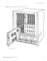
This section provides instructions for removing and installing the management modules in the FSX 800 and FSX 1600 chassis.
Although the modules are dedicated and differ in size, the procedure for installing them is the same. Therefore, this section provides one
procedure that applies to all modules.
Installation precautions
Note the following when removing and installing a management module:
•
The management modules are dedicated, which means that you must install them in the appropriate chassis. If you attempt to
install the FSX management module in the FSX 800, FSX 1600, or other Brocade chassis, the chassis and module will not
function properly. Likewise, if you attempt to install the FSX 800 or FSX 1600 management module in the FSX or other
Brocade chassis, the chassis and module will not function properly.
•
If your Brocade chassis has redundant management modules, you can remove one of the management modules from the
chassis while the chassis is powered on and running. This does not apply to the FSX 800 and FSX 1600 with single
management modules. These devices must be powered down before removing the management module.
•
If your device does not have dual management modules, do not remove the management module while the chassis is powered
on and running. If you attempt to remove this module while the chassis is powered on and running, all traffic being handled by
the system will stop.
•
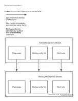
Before removing and replacing an active or standby management module, you need to understand how these actions affect
management module redundancy. Refer to the “Removal and replacement of a management module” section.
•
You cannot mix Second and Third Generation modules together in the same device.
Removing a management module
Before removing a management module, have the following tools on hand:
•
An ESD wrist strap with a plug for connection to the ESD connector on the chassis.
DANGER
For safety reasons, the ESD wrist strap should contain a series 1 megaohm resistor.
•
A #2 Phillips-head or flathead screwdriver.
To remove a management module from the chassis, perform the following tasks.
1. Refer to the “Installation precautions.”
Replacing a management module
Brocade FastIron SX Series Chassis Hardware Installation Guide
120
Part Number: 53-1003613-04
Summary of Contents for FastIron SX
Page 10: ...Brocade FastIron SX Series Chassis Hardware Installation Guide 10 Part Number 53 1003613 04 ...
Page 12: ...Brocade FastIron SX Series Chassis Hardware Installation Guide 12 Part Number 53 1003613 04 ...
Page 46: ...Brocade FastIron SX Series Chassis Hardware Installation Guide 46 Part Number 53 1003613 04 ...
Page 80: ...Brocade FastIron SX Series Chassis Hardware Installation Guide 80 Part Number 53 1003613 04 ...
Page 118: ...Brocade FastIron SX Series Chassis Hardware Installation Guide 118 Part Number 53 1003613 04 ...
Page 158: ...Brocade FastIron SX Series Chassis Hardware Installation Guide 158 Part Number 53 1003613 04 ...
Page 164: ...Brocade FastIron SX Series Chassis Hardware Installation Guide 164 Part Number 53 1003613 04 ...
Page 172: ...Brocade FastIron SX Series Chassis Hardware Installation Guide 172 Part Number 53 1003613 04 ...


