Removing an interface module
To remove an interface module, first perform the steps in section
Before removing an interface module
on page 128, then complete the
following steps.
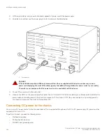
1. Put on the ESD wrist strap and ground yourself by inserting the plug into the ESD connector located in the lower right corner of
the chassis front.
2. Use the #2 Phillips-head or flathead screwdriver to loosen the two screws on the ends of the module.
3. Pull the card ejectors towards you, and away from the module front panel. This action unseats the module from the backplane.
4. Pull the module out of the chassis, and place in an anti-static bag for storage if desired.
5. If you plan to replace the removed module with a different type of module, you must first remove the module configuration. To
do so, enter the
no module
slotnum
command at the global CONFIG level of the CLI, then save the configuration to flash
memory. For example,
device(config)# no module 4
device(config)# exit
device# write mem
NOTE
If you attempt to insert a module of a different type without first removing the previous module configuration, the
system will display an error message.
6. Install a new module in the slot. For information about performing this task, refer to
Installing a new interface module
on page
129.
CAUTION
If you do not install a module or a power supply in a slot, you must keep the slot filler panel in place. If you run the
chassis with an uncovered slot, the system will overheat.
Installing a new interface module
You can install an interface module in the FSX 800 and FSX 1600 chassis while the chassis is powered on and running.
NOTE
Interface modules are interchangeable among all FastIron X Series devices. However, if you install them in a Brocade device
other than a FastIron X Series device, the device and interface modules will not function properly.
DANGER
For safety reasons, the ESD wrist strap should contain a series 1 megaohm resistor.
•
A #2 Phillips-head or flathead screwdriver.
To install a new interface module in the chassis, perform the following tasks.
1. Follow the preparation procedure in the section
Before removing an interface module
on page 128.
2. Put on the ESD wrist strap and ground yourself by inserting the plug into the ESD connector located in the lower right corner of
the chassis front.
3. Remove the module from its packaging.
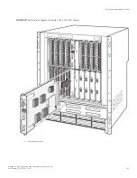
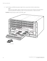
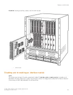
4. Insert the module into the chassis slot as shown in the figures below, and slide the card along the card guide until the ejectors
on either side of the module move close to the module front panel.
5. Push the ejectors in toward the center of the module. This action will fully seat the module in the backplane.
Replacing an interface module
Brocade FastIron SX Series Chassis Hardware Installation Guide
Part Number: 53-1003613-04
129
Summary of Contents for FastIron SX
Page 10: ...Brocade FastIron SX Series Chassis Hardware Installation Guide 10 Part Number 53 1003613 04 ...
Page 12: ...Brocade FastIron SX Series Chassis Hardware Installation Guide 12 Part Number 53 1003613 04 ...
Page 46: ...Brocade FastIron SX Series Chassis Hardware Installation Guide 46 Part Number 53 1003613 04 ...
Page 80: ...Brocade FastIron SX Series Chassis Hardware Installation Guide 80 Part Number 53 1003613 04 ...
Page 118: ...Brocade FastIron SX Series Chassis Hardware Installation Guide 118 Part Number 53 1003613 04 ...
Page 158: ...Brocade FastIron SX Series Chassis Hardware Installation Guide 158 Part Number 53 1003613 04 ...
Page 164: ...Brocade FastIron SX Series Chassis Hardware Installation Guide 164 Part Number 53 1003613 04 ...
Page 172: ...Brocade FastIron SX Series Chassis Hardware Installation Guide 172 Part Number 53 1003613 04 ...

