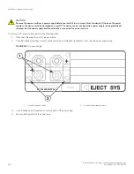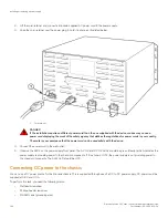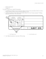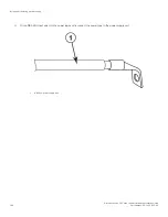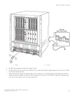
To install a copper or fiber optic module, perform the following tasks.
1. Put on the ESD wrist strap and ground yourself by inserting the plug into the ESD connector located in the lower right corner of
the chassis front.
2. Remove the new module from its protective packaging.
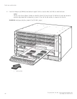
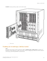
3. Gently insert the copper or fiber optic module into the port until the module clicks into place. The module is keyed to prevent
incorrect insertion.
Cabling a fiber optic module
To cable a fiber optic module, perform the following tasks.
1. Remove the protective covering from the fiber-optic port connectors and store the covering for future use.
2. Before cabling a fiber optic module, Brocade strongly recommends cleaning the cable connectors and the port connectors. For
more information, refer to
Cleaning the fiber optic connectors
on page 119.
3. Gently insert the cable connector or connectors (a tab on each connector should face upward) into the port connector or
connectors until the tabs lock into place.
4. Observe the link and active LEDs to determine if the network connections are functioning properly. For more information about
the LED indicators, refer to
on page 92.
Installing or replacing a power supply
DANGER
Before beginning the installation, see the precautions in “Power precautions.”
This section provides information about the following topics:
•
Determining which power supply has failed, if necessary
•
Replacing an AC power supply
•
Replacing a DC power supply
•
Connecting power to the chassis
•
Verifying proper operation
Determining which power supply failed
To determine which power supply has failed, enter the following command at any CLI command prompt.
device
# show chassis
This command displays status information for the power supplies, as well as information for the fans, and temperature readings for
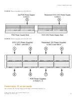
various components in the chassis. The power supplies are numbered in the display. "Power 1" indicates the power supply installed in
power supply slot 1, "power 2" indicates the power supply installed in slot 2, and so on. The two figures below show the power supply
slot numbers.
If the display indicates "Installed (Failed)" for any of the slots, the power supply installed in that particular slot has failed.
Installing or replacing a power supply
Brocade FastIron SX Series Chassis Hardware Installation Guide
134
Part Number: 53-1003613-04
Summary of Contents for FastIron SX
Page 10: ...Brocade FastIron SX Series Chassis Hardware Installation Guide 10 Part Number 53 1003613 04 ...
Page 12: ...Brocade FastIron SX Series Chassis Hardware Installation Guide 12 Part Number 53 1003613 04 ...
Page 46: ...Brocade FastIron SX Series Chassis Hardware Installation Guide 46 Part Number 53 1003613 04 ...
Page 80: ...Brocade FastIron SX Series Chassis Hardware Installation Guide 80 Part Number 53 1003613 04 ...
Page 118: ...Brocade FastIron SX Series Chassis Hardware Installation Guide 118 Part Number 53 1003613 04 ...
Page 158: ...Brocade FastIron SX Series Chassis Hardware Installation Guide 158 Part Number 53 1003613 04 ...
Page 164: ...Brocade FastIron SX Series Chassis Hardware Installation Guide 164 Part Number 53 1003613 04 ...
Page 172: ...Brocade FastIron SX Series Chassis Hardware Installation Guide 172 Part Number 53 1003613 04 ...

