TABLE 27
Desired and abnormal power supply LED states after system power on (continued)
LED
Desired State
Desired State Meaning
Abnormal State
Abnormal State Meaning or
Action
supply and it must be
replaced.
ALM
OFF
No alarms present and the
power supply is in normal
operating condition.
Amber
There is an alarm present
and the power supply is
malfunctioning.
Verify the AC or DC input
and DC output voltages.
If a problem persists after taking action described in this table, contact Brocade’s technical support.
Displaying the status of the power supplies
You can display the status of the power supplies by entering the
show chassis
command at any level of the CLI. The display shows
whether a power supply is installed in the specified power supply slot and the status of the power supply, which can be one of the
following:
•
OK - The power supply is functioning properly and supplying power to the chassis and installed modules.
•
Failed - The power supply is not functioning and is not supplying power to the chassis and installed modules.
Replacing the FSX 800 fan tray
The fan tray in the FSX 800 chassis contains six fans and one fan control module. If any of these components fail, you must replace the
entire fan tray.
NOTE
The fan tray in the FSX 800 chassis is a non-redundant, hot-swappable fan tray.
NOTE
The FSX 800 chassis should not be left running without a fan tray. This will lead to an increase in the chassis temperature, and
can result in a thermal shutdown.
To replace the fan tray, you need the following:
•
A new fan tray, which you can order from Brocade
•
In addition to the above, you might also need a #2 Phillips-head screwdriver.
DANGER
For safety reasons, the ESD wrist strap should contain a series 1 megaohm resistor.
To replace the fan tray, perform the following tasks.
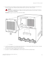
1. Put on the ESD wrist strap and ground yourself by inserting the plug into the ESD connector located in the lower right corner of
the chassis front or use the ESD strap provided with the fan tray kit. Attach the copper tape end to a bare metal area on the
chassis.
Replacing the FSX 800 fan tray
Brocade FastIron SX Series Chassis Hardware Installation Guide
Part Number: 53-1003613-04
149
Summary of Contents for FastIron SX
Page 10: ...Brocade FastIron SX Series Chassis Hardware Installation Guide 10 Part Number 53 1003613 04 ...
Page 12: ...Brocade FastIron SX Series Chassis Hardware Installation Guide 12 Part Number 53 1003613 04 ...
Page 46: ...Brocade FastIron SX Series Chassis Hardware Installation Guide 46 Part Number 53 1003613 04 ...
Page 80: ...Brocade FastIron SX Series Chassis Hardware Installation Guide 80 Part Number 53 1003613 04 ...
Page 118: ...Brocade FastIron SX Series Chassis Hardware Installation Guide 118 Part Number 53 1003613 04 ...
Page 158: ...Brocade FastIron SX Series Chassis Hardware Installation Guide 158 Part Number 53 1003613 04 ...
Page 164: ...Brocade FastIron SX Series Chassis Hardware Installation Guide 164 Part Number 53 1003613 04 ...
Page 172: ...Brocade FastIron SX Series Chassis Hardware Installation Guide 172 Part Number 53 1003613 04 ...

