background image

DATA CENTER 


CONFIGURATION GUIDE 


Configuring an iSCSI SAN Using Brocade FCX Switches 


16 


7.


When the Active unit has finished the authentication process, you will see output that shows the suggested 

assigned stack IDs for each member. You can accept these recommendations, or you can manually 

configure stack IDs. Enter the 

show stack

 command to verify that all units are in the ready state. 

FCX648S Switch# 

show stack


Syntax: show stack 

Here is a sample output after issuing the 

show stack

 command: 

FCX648S Switch# show stack.  

alone: standalone, D: dynamic config, S: static config 

ID   Type       Role    Mac Address    Pri State   Comment                  

1  S FCX648S active  0024.3814.c140   0 local   Ready                         

2  D FCX648S standby 0024.3814.f140   0 remote  Ready                         

    active       standby                                                        

     +---+        +---+                                                         

 -2/1| 1 |2/2--2/1| 2 |2/2-                                                     

 |   +---+        +---+   |                                                     

 |                        |                                                     

 |------------------------|                                                     

Standby unit 2: protocols ready, can failover or manually switch over 

Current stack management MAC is 0024.3814.c140 

Note: no "stack mac" config. My MAC will change after failover. 

Some configuration commands later in this document will require the user to enter unit ID for the unit in the stack 

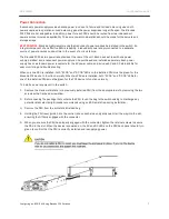
being configured. There are two ways to find the unit ID. Every Brocade FCX switch has stack indicators in front of the 

switch as shown below. These indicators will help the users identify the unit ID assigned to each switch in the stack.  


Another way the unit ID can be verified is by entering  the 

show stack

 command as shown in step 7 above.  

Configuring Dynamic Link Aggregation between switches 

NOTE:

 Skip this section if you are configuring an iSCSI SAN without using link aggregation.  

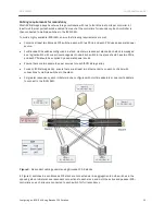
Brocade software supports the IEEE 802.3ad standard for link aggregation. This standard describes the 

Link Aggregation Control Protocol (LACP), a mechanism for allowing ports on both sides of a redundant link 

to form a trunk link (aggregate link), without the need for manual configuration of the ports into trunk 

groups. 

When you enable link aggregation on a group of Brocade ports, the Brocade ports can negotiate with the 

ports at the remote ends of the links to establish trunk groups. By default, link aggregation is disabled on all 

ports. To enable link aggregation on a set of ports, enter commands such as the following at the Interface 

configuration level of the CLI. 

Summary of Contents for FCX 648S

Page 1: ...DATA CENTER Configuring an iSCSI Storage Area Network Using Brocade FCX Switches A step by step guide describing how to install and configure Brocade FCX Switches in an iSCSI Storage Area Network SAN...

Page 2: ...tack 8 Cabling requirements for redundancy 10 Basic Switch Setup andConfiguration 11 Powering On the System 11 Connecting to a PC or Terminal 11 Using the CLI 12 Configuring IP Addresses 12 Assigning...

Page 3: ...d support designating one or more through Link Aggregation Groups ports for inter switch links Brocade FCX stand alone switches provide up to 40Gbps full duplex bandwidth for ISL For stacking switches...

Page 4: ...one cable is required per switch or one per stack in a Brocade FCX stack The Ethernet cable must be connected to a corporate or data center network that allows the administrator to manage the switch r...

Page 5: ...om an independent circuit breaker As with any equipment a filter or surge suppressor is recommended Rack Installation As noted in the previous section Brocade FCX switches can be installed on a deskto...

Page 6: ...Remove the rack mount kit from the shipping carton The kit contains two L shaped mounting brackets and mounting screws 3 Attach the mounting brackets to the each side of the device using the provided...

Page 7: ...er cable and includes AC and DC status LEDs for easy monitoring and troubleshooting When only one PSU is installed both AC OK and DC OK LEDs on the installed PSU must be green for the Brocade FCX devi...

Page 8: ...the stack link so if one link fails stack communications can be maintained Figure 1 illustrates a ring topology stacking configuration In a redundant iSCSI deployment of stacked Brocade FCX switches...

Page 9: ...of an LC LC MM Fiber cable into one of the top unit s SFP stacking ports 2 Plug the other end of the cable into one of the stacking ports of the next unit 3 Repeat steps 1 and 2 for each unit in the s...

Page 10: ...managed as a logical switch with one active management node Each switch in the stack should have two PSUs and each PSU should be supplied by a separate power source Ensure there are two separate power...

Page 11: ...tlet Connecting to a PC or Terminal To manage the switch connect the console serial port on the switch to a management station such as a PC running a terminal emulation application for example HyperTe...

Page 12: ...r commands or options the CLI understands what you are typing Configuring IP Addresses At least one IP address must be configured using the serial connection to the CLI before you can manage each swit...

Page 13: ...mand to save changes FCX648S Switch config ip address 192 168 1 252 255 255 255 0 FCX648S Switch config write memory Syntax ip address ip address sub net mask 5 Set a default gateway address for the s...

Page 14: ...ecure to avoid allowing access to the SAN from the LAN The management port is an out of band port that customers can use to manage their switches without interfering with the in band ports The managem...

Page 15: ...mands to configure the stack on a Brocade FCX 648 S FCX648S Switch config t FCX648S Switch config stack enable FCX648S Switch config write mem Enter these commands to configure the stack on an Brocade...

Page 16: ...to enter unit ID for the unit in the stack being configured There are two ways to find the unit ID Every Brocade FCX switch has stack indicators in front of the switch as shown below These indicators...

Page 17: ...rnet 1 3 2 FCX648S Switch config if e10000 1 3 2 link aggregate active Syntax interface ethernet stack unit slotnum portnum link aggregate active To configure link aggregation on a Brocade FCX 648 E u...

Page 18: ...02 1w FCX648S Switch config write mem Syntax spanning tree 802 1w BEST PRACTICE For iSCSI deployments Brocade recommends that spanning tree be disabled on all access ports Access ports are the switch...

Page 19: ...unit 1 FCX648S Switch config symmetric flow control enable unit 2 FCX648S Switch config write mem Syntax no symmetric flow control enable unit unit_ID NOTE Refer to the section on stack configuration...

Page 20: ...maximum frame size of 1 500 bytes so most devices use 1 500 as their default MTU Jumbo frames are Ethernet frames with more than 1 500 bytes MTU Conventionally jumbo frames can carry up to 9 000 bytes...

Page 21: ...connection and click View Status The Local Area Connection X Status displays 3 Click Properties 4 Click Configure 5 Click the Advanced tab 6 From the Property list select Jumbo Packet 7 From the Valu...

Page 22: ...ibuting the load across different switches and different switch ports SWITCH CONFIGURATION DUMP This section shows a sample output of the running config from a Brocade FCX stack configured per the ins...

Page 23: ...e ethernet 2 1 15 flow control neg on interface ethernet 2 1 16 flow control neg on interface ethernet 2 2 3 link aggregate active interface ethernet 2 2 4 link aggregate active end telnet STACK1 conf...

Page 24: ...tems Inc All Rights Reserved 06 10 GA CG 285 00 Brocade the B wing symbol BigIron DCFM DCX Fabric OS FastIron IronView NetIron SAN Health ServerIron TurboIron and Wingspan are registered trademarks an...

Reviews: