background image

2

Brocade Mobility RFS9510 Controller Installation Guide

53-1002918-01

Site preparation

1

Do not install this equipment or work with its power circuits during thunderstorms or other 
weather conditions that could cause a power surge.

Verify there is adequate ventilation around the device, and ambient temperatures meet 
equipment operation specifications.

Site preparation

Consult your site survey and network analysis reports to determine specific equipment 
placement, power drops, and so on. 

Assign installation responsibility to the appropriate personnel.

Identify and document where all installed components are located.

Provide a sufficient number of power drops for your equipment.

Ensure adequate, dust-free ventilation to all installed equipment.

Identify and prepare Ethernet and console port connections.

Verify cable lengths are within the maximum allowable distances for optimal signal 
transmission.

Getting started

This guide provides a pre-installation checklist and instructions for installing the Mobility RFS9510 
Controller, accessing the 

Graphical User Interface

 (GUI), and performing initial configuration.

Pre-installation checklist

Location & equipment

Mobility RFS9510 Controller shipping container contents:

Mobility RFS9510 Controller 

Locking front bezel with keys

Mounting rail kit

Brocade Mobility RFS9510 Controller Installation Guide

 (this document)

NOTE

Keep the front bezel keys in a secure location which can only be accessed by authorized personnel.

Additional equipment recommended

Standard, grounded 100-240 VAC 50/60 Hz connection

UPS (uninterruptable power supply)

Standard 19-inch rack (2U height) with mounting rails.

Summary of Contents for RFS9510

Page 1: ...53 1002918 01 04 April 2014 Brocade Mobility RFS9510 Controller Installation Guide...

Page 2: ...n contained herein or the computer programs that accompany it The product described by this document may contain open source software covered by the GNU General Public License or other open source lic...

Page 3: ...pecifications Electrical characteristics 7 Physical specifications 7 Environmental specifications 7 Power specifications 7 Chapter 3 Hardware Installation Power protection 9 Hardware installation 9 In...

Page 4: ...Requirements FCC 22 Radio Frequency Interference Requirements Canada 22 Marking and European Economic Area EEA 22 Statement of Compliance 22 Japan Voluntary Control Council for Interference VCCI Clas...

Page 5: ...ollowing graphical alerts are used in this document to indicate notable situations NOTE Tips hints or special requirements that you should take note of CAUTION Care is required Disregarding a caution...

Page 6: ...ion to all installed equipment Identify and prepare Ethernet and console port connections Verify cable lengths are within the maximum allowable distances for optimal signal transmission Getting starte...

Page 7: ...d or cooled For proper airflow keep the front and back sides of the controller clear of obstructions and away from the exhaust of other equipment CAUTION The recommended ambient operating temperature...

Page 8: ...should be given to installing the appliance in an environment compatible with the maximum ambient temperature Tma specified by the manufacturer Reduced Air Flow Installation of the Mobility RFS9510 C...

Page 9: ...o ensure the accuracy and completeness of this document However if you find an error or an omission or you think that a topic needs further development we want to hear from you Forward your feedback t...

Page 10: ...6 Brocade Mobility RFS9510 Controller Installation Guide 53 1002918 01 Warranty coverage 1...

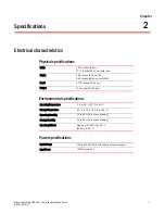
Page 11: ...th rails Height 3 44 inches 8 74 cm 2U 33 0 inches 83 82 cm with CMA Depth 27 75 inches 70 49 cm Weight 47 pounds 21 319 kg s Operating Temperature 0 C to 35 C 32 F to 95 F Storage Temperature 40 C to...

Page 12: ...8 Brocade Mobility RFS9510 Controller Installation Guide 53 1002918 01 Electrical characteristics 2...

Page 13: ...ection device between the electricity source and the Mobility RFS9510 Controller Install an Uninterruptible Power Supply UPS A UPS provides continuous power during a power outage Some UPS devices have...

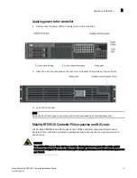
Page 14: ...roller to the network 4 Connect a standard VGA monitor to the video port on the back of the controller 5 Connect a keyboard and mouse to the USB ports on the back of the controller 6 Gently press the...

Page 15: ...front bezel keys in a secure location only accessed by authorized personnel Mobility RFS9510 Controller PCIe expansion and NIC cards The Mobility RFS9510 Controller supports two 10GBe Peripheral Compo...

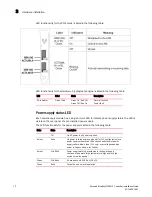
Page 16: ...ly is listed in the following table LED Color State Description DC Indicator Green Red Green On Red Off Green Off Red On Normal function Power fault Color State Description Off No AC power to all powe...

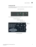
Page 17: ...Guide 13 53 1002918 01 Hardware installation 3 Control panel LEDs The control panel houses six LEDs indicating the controller s operating state The LEDs are visible when the front bezel is attached Re...

Page 18: ...ription NIC1 NIC2 Green On Blink NIC link Normal NIC activity Power and sleep Green On Blink Power on Sleep mode System status Green Amber On Blink On Blink Normal operation Degraded operation Critica...

Page 19: ...table below Button Function Power Sleep Turns the system power on off ID Toggles the ID LED on and off The server board ID LED is visible on the back of the controller to allow for server identificati...

Page 20: ...16 Brocade Mobility RFS9510 Controller Installation Guide 53 1002918 01 Hardware installation 3...

Page 21: ...n Ethernet cable to one of the ports on the back of the Mobility RFS9510 Controller and connect the other end to a computer with a working Web browser 2 Set the computer to use an IP address between 1...

Page 22: ...ion Guide 53 1002918 01 Using the Mobility RFS9510 controller management interface 4 6 Click Login You are then prompted to change your password 7 Enter a new password then enter it again to confirm i...

Page 23: ...nagement interface 4 9 Click OK The Mobility RFS9510 Controller Dashboard is displayed You have now established a connection to the Mobility RFS9510 Controller management interface 10 For software con...

Page 24: ...20 Brocade Mobility RFS9510 Controller Installation Guide 53 1002918 01 Using the Mobility RFS9510 controller management interface 4...

Page 25: ...perate the equipment CAUTION Operation of the device without regulatory approval is illegal CAUTION This product is designed and approved for indoor deployments only and is not intended to be connecte...

Page 26: ...ce at his own expense Radio Frequency Interference Requirements Canada This Class A digital apparatus complies with Canadian ICES 003 Cet appareil num rique de la classe A est conforme la norme NMB 00...

Page 27: ...al and Electronic Equipment WEEE 5 Waste Electrical and Electronic Equipment WEEE For information on WEEE please go to http www brocade com company corporate responsibility corporate citizenship produ...

Reviews: