background image

18

Brocade ServerIron ADX Installation Guide

53-1002405-01

Installing ServerIron ADX

2

Preparing the installation site

This section describes how to prepare for installation.

Cabling infrastructure

Ensure that the proper cabling is installed at the site.

For information on cabling, refer to 

“Installing power supplies”

 on page 26 and 

“Attaching a 

management station”

 on page 36.

DANGER

The intra-building port(s) of the equipment or subassembly is suitable for connection to 
intra-building or unexposed wiring or cabling only. The intra-building port(s) of the equipment or 
subassembly MUST NOT be metallically connected to interfaces that connect to the OSP or its 
wiring. These interfaces are designed for use as intra-building interfaces only (Type 2 or Type 4 
ports as described in GR-1089-CORE, Issue 4) and require isolation from the exposed OSP 
cabling. The addition of Primary Protectors is not sufficient protection in order to connect these 
interfaces metallically to OSP wiring.

Installation location

Before installing a ServerIron ADX, plan its location and orientation relative to other devices and 
equipment. For cooling purposes, allow a minimum of six inches of space between the sides, front, 
and the back of the chassis and walls or other obstructions. If a chassis is installed within a 
perforated enclosure, the perforations must have openings of at least 60 percent of the surface.

The ServerIron ADX series are suitable for installation in Network Telecommunications facilities and 
locations where the NEC (National Electric Code) apply.

Installing the ServerIron ADX chassis in a rack

This section describes the following tasks:

“Preparing to mount a ServerIron ADX chassis in a rack”

“Mounting a ServerIron ADX chassis in a rack”

“Removing the slot blanks - ServerIron ADX chassis devices”

Preparing to mount a ServerIron ADX chassis in a rack

NOTE

Due to the weight of a fully loaded chassis device, Brocade recommends mounting a chassis in a 
rack before installing additional modules and power supplies.

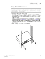
For each ServerIron ADX chassis that you install in a rack, you must provide four standard #12-24 
pan-head screws with which to mount and secure the chassis. Before performing this task, you 
should have an assembled rack and a #2 Phillips-head screwdriver.

Summary of Contents for SERVERIRON ADX 1000

Page 1: ...1 September 2011 Brocade ServerIron ADX Installation Guide Supporting ServerIron ADX 1000 ServerIron ADX 1000F ServerIron ADX 4000 ServerIron ADX 8000 and ServerIron ADX 10000 Model SI1000 SI1000F SI4...

Page 2: ...es office for information on feature and product availability Export of technical data contained in this document may require an export license from the United States government Brocade Communications...

Page 3: ...devices 1 ServerIron ADX 1000 1 ServerIron ADX 1000F 2 ServerIron ADX chassis devices 2 ServerIron ADX 4000 2 ServerIron ADX 10000 ADX 10K chassis 4 ServerIron ADX Chassis device modules 5 Ethernet i...

Page 4: ...urce 37 Uninstalling ServerIron ADX modules 38 Uninstalling ServerIron ADX 4000 8000 10000 interface modules 38 Uninstalling an Application Switch module 39 Uninstalling a Management module 40 Uninsta...

Page 5: ...re specifications 57 Power specifications 57 Physical dimensions 58 Operating environment 58 Storage environment 59 Safety agency approvals 59 Electromagnetic approvals 59 Port specifications 59 Conso...

Page 6: ...vi Brocade ServerIron ADX Installation Guide 53 1002405 01...

Page 7: ...with the following protocols if applicable to your network IP RIP OSPF BGP ISIS IGMP PIM DVMRP and VRRP Supported hardware and software In those instances in which procedures or parts of procedures do...

Page 8: ...these conventions bold text Identifies command names Identifies the names of user manipulated GUI elements Identifies keywords and operands Identifies text to enter at the GUI or CLI italic text Prov...

Page 9: ...hazardous to you Safety labels are also attached directly to products to warn of these conditions or situations Getting technical help or reporting errors Brocade is committed to ensuring that your i...

Page 10: ...x Brocade ServerIron ADX Installation Guide 53 1002405 01...

Page 11: ...2 application cores and hardware SSL Acceleration 16 x 1 Gigabit Ethernet ports with 4 applications cores and hardware SSL Acceleration 16 x 1 Gigabit Ethernet ports and 2 x 10 Gigabit Ethernet ports...

Page 12: ...10 Gigabit Ethernet fiber SFP ports and one AC power supply The capacity on demand facilitates pay as you grow with ServerIron ADX 1000F and enables you to add performance ports and features SSL IPv6...

Page 13: ...owing components Two Ethernet Interface Modules Two Application Services Modules ASM One Management Module MM One Switch Fabric Module SFM One fan tray Two AC or DC power supplies one required one red...

Page 14: ...One fan tray Brocade ServerIron ADX 10000 r w P e l o s n o C M S A P B 1 2 3 4 5 6 7 8 n I t u O e l u d o M h c t i w S n o i t a c i l p p A M S A I S r w P e l o s n o C M S A P B 1 2 3 4 5 6 7 8...

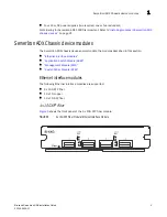
Page 15: ...ron ADX Chassis device modules The ServerIron ADX chassis devices accommodate the modules described in this section Ethernet interface modules Application Switch Module ASM Management Module MM Switch...

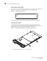
Page 16: ...Switch Module ASM Figure 8 shows the Application Switch Module ASM front panel FIGURE 8 ASM Front Panel NOTE Starting with Brocade ServerIron ADX release 12 2 1 the label for the Application Switch M...

Page 17: ...pability of an ASM4 to that of an ASM8 The ASM4 license is tied to the ASM module and not to the chassis Consequently a license can be purchased to upgrade the ASM4 to use all eight available Applicat...

Page 18: ...ule Front Panel The front panel includes a LED that when lit indicates that the module is receiving power SSL Expansion Module A ServerIron ADX management module can be upgraded to provide hardware ba...

Page 19: ...rIron ADX 10000 accommodate up to four power supplies AC or DC with two required and one or two redundant Because power is supplied over a common power bus any power supply purchased in addition to th...

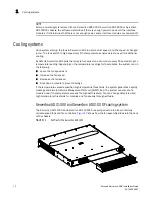
Page 20: ...a temperature reading Depending on the temperature readings for the modules the system can do the following Leave the fan speed as is Increase the fan speed Decrease the fan speed Shut down a module...

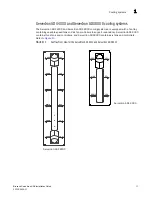
Page 21: ...ray containing variable speed fans and six fan controllers to support redundancy ServerIron ADX 4000 contains three fans and controllers and ServerIron ADX 8000 contains six fans and controllers Refer...

Page 22: ...peed fans to support redundancy The fan tray has a fan filter that can be changed while the ServerIron ADX 10000 is in operation Refer to Figure 14 FIGURE 14 Fan Tray Front View for the ServerIron ADX...

Page 23: ...ountry The mark is your assurance that the power cord can be used safely with the device CAUTION Product contains ESD sensitive devices use proper ESD mitigation procedures such as ESD grounding wrist...

Page 24: ...ld waste Contact your local waste disposal agency for the address of the nearest battery deposit site DANGER All fiber optic interfaces use Class 1 lasers CAUTION Do not install the device in an envir...

Page 25: ...CAUTION Ensure that the device does not overload the power circuits wiring and over current protection To determine the possibility of overloading the supply circuits add the ampere amp ratings of all...

Page 26: ...eplaced while the ServerIron ADX chassis is powered on and running However Brocade recommends that you disconnect the power supply from AC power before installing or removing the supply The device can...

Page 27: ...e Gauge AWG The ground wire should have an agency approved crimped connector provided with the chassis attached to one end with the other end attached to building ground The connector must be crimped...

Page 28: ...rIron ADX plan its location and orientation relative to other devices and equipment For cooling purposes allow a minimum of six inches of space between the sides front and the back of the chassis and...

Page 29: ...rIron ADX 4000 ServerIron ADX 8000 or ServerIron ADX 10000 chassis with the fewest modules should be on top a chassis with more modules than the top chassis in the middle and a fully populated chassis...

Page 30: ...e rack using star washers Additionally if any single hole grounding lugs are used star washers shall be used as a means to prevent rotation of the lug 6 Repeat step 2 through step 5 to mount each subs...

Page 31: ...t OSP or its wiring These interfaces are designed for use as intra building interfaces only Type 2 or Type 4 ports as described in GR 1089 CORE Issue 4 and require isolation from the exposed OSP cabli...

Page 32: ...hips with the following components installed see shaded slots in Figure 18 Two SFMs Fan tray Two power supplies FIGURE 18 Slot Ordering for the ServerIron ADX 10000 Chassis PS SLOT 1 ServerIron 4000 F...

Page 33: ...ing on hand An ESD wrist strap with a plug for connection to the ESD connector on the chassis NOTE For safety reasons the ESD wrist strap should contain a 1 meg ohm series resistor A large flat head s...

Page 34: ...dule front panel by pushing them in and turning them clockwise Then tighten the screws further using the flat head screwdriver Installing an SSL Expansion module onto a management module The SSL upgra...

Page 35: ...See Table 1 for a and Figure 20 for a list and illustration of the kit components 2 Place the Management module on a table or flat surface 3 Line up the posts on the Management module with the holes...

Page 36: ...river fasten the SSL Expansion module to the ServerIron ADX Management Module with the six screws FIGURE 22 Installing the six screws Installing power supplies This section describes how to install po...

Page 37: ...he power supply from its packaging 3 Insert the power supply into the empty power supply slot using the guides provided on either side of the slot Figure 23 CAUTION Carefully follow the mechanical gui...

Page 38: ...ServerIron ADX chassis device equipped for redundancy For the ServerIron ADX 8000 and ServerIron ADX 10000 chassis you can plug power supplies into any of the power slots in any order To install a pow...

Page 39: ...nnecting AC power AC power is supplied through an AC power cord The cord is installed at the back of the ServerIron ADX 1000 chassis and at the front of the ServerIron ADX 4000 ServerIron ADX 8000 and...

Page 40: ...ower Connections on the ServerIron ADX 8000 Chassis FIGURE 28 AC Power Connections on the ServerIron ADX 10000 Chassis 100 240 VAC 48 VDC SEE REAR LABEL PS1 PS2 PS1 PS2 PS3 PS4 100 240 VAC 48 VDC SEE...

Page 41: ...The ground wire should have an agency approved crimped connector provided with the chassis attached to one end with the other end attached to building ground The connector must be crimped with the pr...

Page 42: ...Iron ADX 1000 follow these steps 1 Insert the wires into the DC wiring assembly Figure 29 2 Use the wire tightening screws to secure the wires FIGURE 29 The ServerIron ADX 1000 DC Power Supply 3 Push...

Page 43: ...em use a ground wire of at least 6 American Wire Gauge AWG The ground wire should have an agency approved crimped connector provided with the chassis attached to one end with the other end attached to...

Page 44: ...on ADX 8000 and ServerIron ADX 10000 DC Power Supply 2 Use a Phillips head screwdriver to remove each of the power lugs 3 Crimp 8 AWG power supply wire into the power lugs and reconnect the power lugs...

Page 45: ...work FIGURE 32 Crimping the Power Supply Wire in the Lug 4 Re attach the transparent cover over the power supply lugs that was removed in Step 1 5 Connect the wire to your DC power source making sure...

Page 46: ...e port which has a male DB 9 serial connector and 10BaseT 100Base TX Ethernet port which has an RJ 45 UTP connector allow you to attach a PC or terminal From the console port you can access the Server...

Page 47: ...t the system may overheat 2 If you are supplying a DC power source to a ServerIron ADX chassis attach the power cables to the DC power supply as described in Connecting DC power to a chassis on page 3...

Page 48: ...lling a Management module Uninstalling a Switch Fabric module Uninstalling a Fan module Uninstalling a Power Supply Uninstalling ServerIron ADX 4000 8000 10000 interface modules When removing an inter...

Page 49: ...ing an Application Switch Module ASM from a ServerIron 4000 ServerIron 8000 or ServerIron 10000 you should perform the following actions in the order shown 1 Execute the disable module command for the...

Page 50: ...d enable standby mgmt module commands is described in the following Syntax disable standby mgmt module Syntax enable standby mgmt module Uninstalling a Switch Fabric module When removing a Switch Fabr...

Page 51: ...Redundant power supplies can be added during operation When a power supply is removed or added during operation messages are sent to the console and logged indicating that the supply is present or not...

Page 52: ...tomatically detected and brought online NOTE You must make certain that there is no configuration mismatch for the Interface module in that slot Installing an Power Supplies in a running system Provid...

Page 53: ...mation on matching each LED to the correct port Blinking The port is transmitting and receiving packets Off A link is not established with the remote port and no traffic is being transmitted or receiv...

Page 54: ...put power Green blinking Supply has AC input power but DC output is not enabled Green steady Supply has AC input power is enabled and has good DC output Amber steady Power supply has failed DC refer t...

Page 55: ...rIron ADX 1000F and Figure 36 shows the DC LED FIGURE 35 AC Power Supply LED ServerIron ADX 1000 FIGURE 36 DC Power Supply LED ServerIron ADX 1000 1 LEDs for Power Supplies 3 LEDs for 1G Interface Por...

Page 56: ...000 LED Desired State Meaning Abnormal State Meaning Action Application Switch Module ASM Pwr On The module is receiving power Off The module is not receiving power You can do the following Make certa...

Page 57: ...not receiving power You can do the following Make certain that the module is installed properly For more information refer to Installing modules in ServerIron ADX chassis devices on page 21 If using A...

Page 58: ...le is installed properly For more information refer to Installing modules in ServerIron ADX chassis devices on page 21 If using AC power supplies see the entry for the AC power supply LED in this tabl...

Page 59: ...emote port and no traffic is being transmitted or received 12 x 1G SFP Fiber Ethernet Interface Module Pwr On The module is receiving power Off The module is not receiving power You can do the followi...

Page 60: ...lies DC DC IN Green steady The power supply is receiving DC power from a DC power source Off The power supply is not receiving power from a DC power source You can do the following Make sure that the...

Page 61: ...rnet Interface Module FIGURE 37 Interpreting LEDs on the 4 x 10G XFP Fiber Ethernet Interface Module Figure 38 shows how to match the LEDs to ports on the 12 x 1G Copper Ethernet Interface Module FIGU...

Page 62: ...ports on the 12 x 1G SFP Fiber Ethernet Interface Module Replacing a Fan Tray You can replace the fan tray in the ServerIron ADX chassis NOTE Fan trays are hot swappable Hot swapping fan trays should...

Page 63: ...fan tray out 4 Slide the new fan tray in and tighten the screws to secure it to the chassis 5 Plug the chassis back in and power up Replacing the ServerIron ADX 4000 or ServerIron ADX 8000 Fan Tray To...

Page 64: ...follow these steps 1 Power down and unplug the chassis 2 Use a 2 phillips screwdriver to loosen the captive screws These are the silver screws 3 Use the handles to pull the fan tray from the chassis...

Page 65: ...Brocade ServerIron ADX Installation Guide 55 53 1002405 01 Replacing a Fan Tray 2 FIGURE 42 Replacing a Fan from a ServerIron ADX 10000 Fan Tray Handle Handle Captive Screw silver Captive Screw silver...

Page 66: ...iner away from the fan assembly shown in Figure 43 FIGURE 43 Air Filter Removal and Replacement for the ServerIron ADX 10000 3 Pull the fan filter away from the filter retainer The fan filter is held...

Page 67: ...ains the power specifications for the ServerIron ADX chassis Table 4 provides the maximum power calculations Table 5 lists the maximum power consumption in watts for ServerIron ADX 4000 ServerIron ADX...

Page 68: ...atings Power Supply Input Voltage Range Input Current Inrush Current Maximum Output AC 100 240Vac 85 264Vac 7A max 30A peak 25 C 500W DC 48Vdc 40Vdc to 60Vdc 15A max 25A peak 25 C 500W TABLE 7 ServerI...

Page 69: ...nology Equipment Electromagnetic approvals FCC Part 15 Subpart B Class A EN 55022 CE mark Class A EN55024 CE mark Immunity for Information Technology Equipment ICES 003 Canada Class A AS NZ 55022 Aust...

Page 70: ...male DB 9 connector as shown in Figure 44 For information about how you can use this port refer to Attaching a PC or terminal to the Console port or Ethernet port on page 36 FIGURE 44 Console Port Pin...

Page 71: ...odule Ethernet port to a network on page 37 TABLE 11 Management Port Pin Assignments Pin Number MDI X Ports 1 TD 2 TD 3 RD 4 Not used 10BaseT CMT 100BaseTX 5 Not used 10BaseT CMT 100BaseTX 6 RD 7 Not...

Page 72: ...62 Brocade ServerIron ADX Installation Guide 53 1002405 01 Port specifications A...

Page 73: ...ssis ServerIron ADX 8000 chassis basics 8 RU form factor Four hot pluggable AC or DC power supplies two two redundant Lnk Act 1 2 PS1 PS2 PS3 PS4 100 240 VAC 48 VDC SEE REAR LABEL BP In Out ASM Consol...

Page 74: ...ules MM Two Switch Fabric Modules SFM One fan tray Four AC or DC power supplies two required one or two redundant Slot ordering for ServerIron ADX 8000 is important Refer to Installing modules in Serv...

Page 75: ...Brocade ServerIron ADX Installation Guide 65 53 1002405 01 ServerIron ADX 8000 B...

Page 76: ...66 Brocade ServerIron ADX Installation Guide 53 1002405 01 ServerIron ADX 8000 B...

Page 77: ...in which case the user will be required to correct the interference at his own expense CAUTION Changes or modifications made to this device which are not expressly approved by the party responsible fo...

Page 78: ...ise When such trouble occurs the user may be required to take corrective actions This is Class A product based on the standard of the Voluntary Control Council For Interference by Information Technolo...

Page 79: ...s a Class A device so sellers or users should be aware of this If it is sold or purchased incorrectly it should be exchanged with a home apparatus Class B BMSI STATEMENT TAIWAN English translation of...

Page 80: ...70 Brocade ServerIron ADX Installation Guide 53 1002405 01 BMSI STATEMENT TAIWAN C...

Page 81: ...ments dot s d un bloc d alimentation en courant continu sont con us pour l installation dans des zones acc s r glement uniquement Une zone acc s r glement est un local qui n est accessible que par le...

Page 82: ...er 40 C 104 F PRECAUCI N No instale el instrumento en un entorno en el que la temperatura ambiente de operaci n pueda exceder los 40 C 104 F CAUTION Ensure that the device does not overload the power...

Page 83: ...migten Crimpverbinder angebracht werden der mit einem ordnungsgem en Werkzeug gecrimpt wurde MISE EN GARDE Pour les syst mes C C r f rences du bloc d alimentation C C RPSDC FGS utilisez un fil de mise...

Page 84: ...Startup Konfig nur f r neue Systeme Wenn Sie diesen Befehl in ein bereits konfiguriertes System eingeben l scht der Befehl die Konfiguration Falls Sie aus Versehen die Konfiguration eines bereits konf...

Page 85: ...ir sobrecalentamiento CAUTION Risk of explosion if battery is replaced by an incorrect type Replace the battery only with the same or equivalent type recommended by the manufacturer Lithium battery is...

Page 86: ...me assurez vous de la pr sence d un disjoncteur de 30 amp res minimum 48 V C C double coupure sur l entr e vers le bloc d alimentation Les c bles d alimentation pour le produit doivent tre en fils de...

Page 87: ...ns where the NEC National Electric Code apply VORSICHT F r NEBS konforme Installationen Ger te mit Wechselspannungsversorgung sind nur zur Installation in Bereichen mit Zugangsbeschr nkung bestimmt Ei...

Page 88: ...t sind Ethernet Schnittstellenmodule d rfen nur in Einsch be eingesetzt werden die als Einsch be f r Schnittstellenmodule gekennzeichnet sind Netzteile d rfen nur in Einsch be eingesetzt werden die mi...

Page 89: ...spec ficamente para ellos Por ejemplo se debe instalar un MM en una de las ranuras MM Los m dulos de interfaz Ethernet deben instalarse en las ranuras marcadas para los m dulos de interfaz CAUTION AC...

Page 90: ...ada de forma que se pueda conectar a los dos tornillos de conexi n a tierra del compartimento Antes de engarzar el cable de conexi n a tierra a la patilla de conexi n a tierra proporcionada Panduit LC...

Page 91: ...ilizarse exclusivamente con dispositivos Serverlron El suministro de energ a genera una cantidad de energ a importante Si instala el suministro de energ a en un dispositivo que no sea Serverlron se da...

Page 92: ...bel um es an die Srromquelle anzuschlie en DANGER V rifiez que les circuits de sources d alimentation sont bien mis la terre puis utilisez le cordon d alimentation fourni avec le dispositif pour le co...

Page 93: ...lectrique du secteur le personnel risque d tre bless ou d endommager l alimentation lectrique ou d autres composants PELIGRO Los suministros de corriente alterna pueden desmontarse y reemplazarse cuan...

Page 94: ...den noch mit hoher Geschwindigkeit drehen DANGER Faites attention de ne pas accidentellement ins rer vos doigts dans le bo tier du ventilateur lorsque vous l enlevez du ch ssis Il est possible que le...

Page 95: ...bestimmt Der bzw die Intra Building Ports des Ger ts und der Baugruppen D RFEN NICHT metallisch mit Schnittstellen verbunden werden die an die Netzinfrastruktur bzw dessen Verkabelung angeschlossen s...

Reviews: