SX6 blade port numbering and trunking
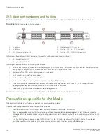
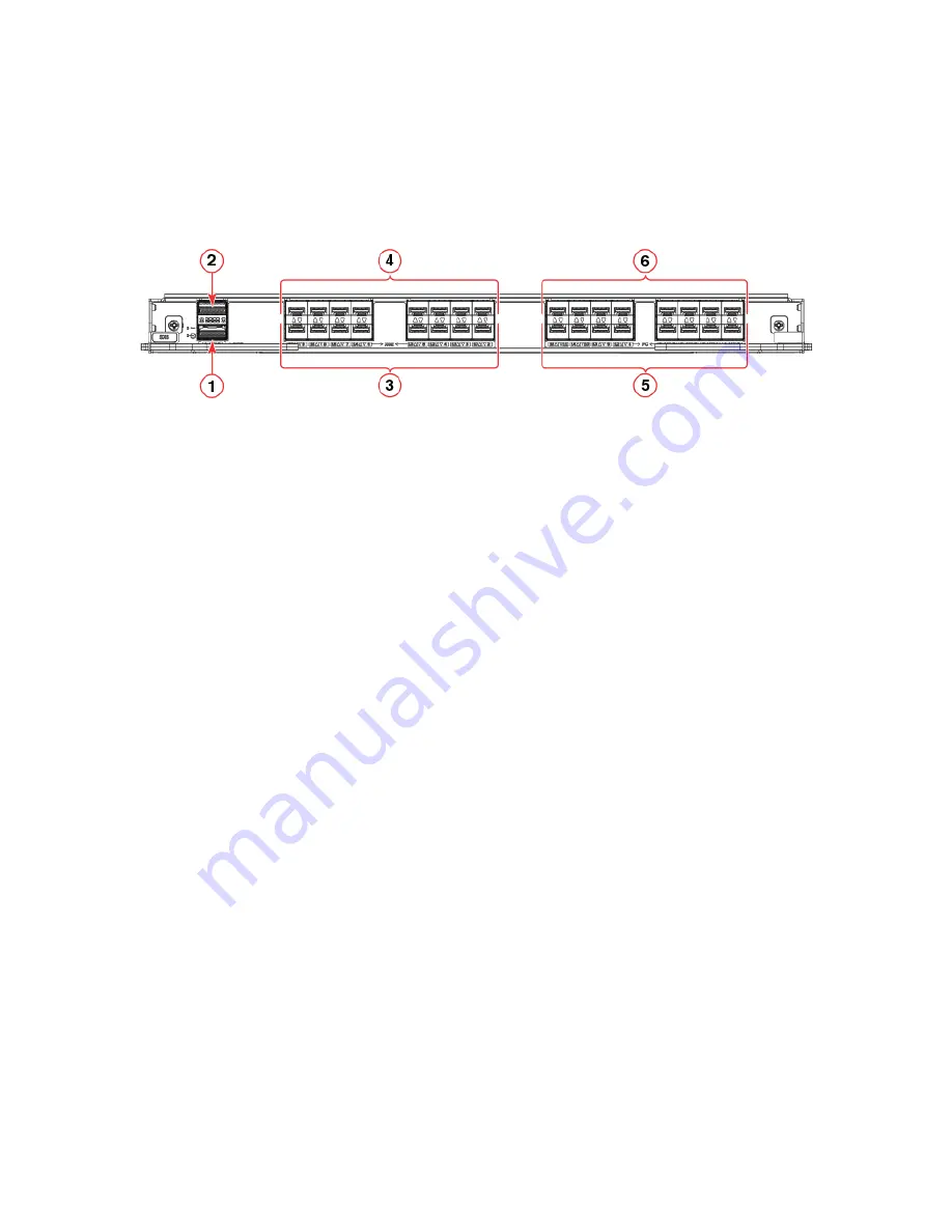
The following illustration shows how ports are numbered on the blade. Ports are labeled as 10GE, 40 GbE, and FC on the blade.
FIGURE 52
SX6 Extension blade port numbering
1.
40 GbE port 0
2.
40 GbE port 1
3.
10/1 GbE ports 2–9 (right to left)
4.
10/1 GbE ports 10–17 (right to left)
5.
FC ports 0, 1, 2, 3, 8, 9, 10, 11 (right to left)
6.
FC ports 4, 5, 6, 7, 12, 13, 14, 15 (right to left)
Following are the eight-port Fibre Channel port groups for configuring trunk groups or "trunks":
•
Port group 0: ports 0–7
•
Port group 1: ports 8–15
Following are the requirements for forming trunk groups:
•
All ports in a trunk group must belong to the same port group. For example, to form an 8-port trunk select all eight ports from
port group 0 or port group 1. You cannot use ports from each port group for the trunk.
•
You can use from 1–8 ports in a port group to form a trunk.
•
Ports must be running at the same speed.
•
Ports must be configured for the same distance.
•
Ports must have the same encryption, compression, QoS, and FEC settings.
•
Trunk groups must be created between Brocade switches (or Brocade adapters in the case of F_Port trunking). Brocade
trunking is proprietary and is not supported on M-EOS or third-party switches.
•
There must be a direct connection between participating switches.
For full details on trunking requirements and configuration, refer to the
Brocade Fabric OS Administration Guide
.
Precautions specific to the blade
This document describes how to remove and replace a port or extension blade.
Observe the following precautions when replacing these blades:
•
The SX6 extension and FC32-48 port blade can only be installed in Brocade X6 Directors.
•
Wear an appropriately grounded ESD wrist strap when handling and installing device blades and cards. Follow electrostatic
discharge (ESD) precautions. Wear a wrist grounding strap connected to chassis ground (if the chassis is plugged in) or a bench
ground.
•
Install port and extension blades only in slots 3–4 and 7–8. Slots 5 and 6 are reserved for CR32-4 blades. These blades
cannot be installed in other slots as guide pins and connectors in each slot allow only specific blade types.
Precautions specific to the blade
Brocade X6-4 Director Hardware Installation Guide
134
53-1004106-07
Summary of Contents for X6-4
Page 12: ...Brocade X6 4 Director Hardware Installation Guide 12 53 1004106 07...
Page 20: ...Brocade X6 4 Director Hardware Installation Guide 20 53 1004106 07...
Page 28: ...Brocade X6 4 Director Hardware Installation Guide 28 53 1004106 07...
Page 64: ...Brocade X6 4 Director Hardware Installation Guide 64 53 1004106 07...
Page 86: ...Brocade X6 4 Director Hardware Installation Guide 86 53 1004106 07...
Page 102: ...Brocade X6 4 Director Hardware Installation Guide 102 53 1004106 07...
Page 130: ...Brocade X6 4 Director Hardware Installation Guide 130 53 1004106 07...
Page 140: ...Brocade X6 4 Director Hardware Installation Guide 140 53 1004106 07...
Page 166: ...Brocade X6 4 Director Hardware Installation Guide 166 53 1004106 07...
Page 196: ...Brocade X6 4 Director Hardware Installation Guide 196 53 1004106 07...
Page 200: ...Brocade X6 4 Director Hardware Installation Guide 200 53 1004106 07...
Page 204: ...Brocade X6 4 Director Hardware Installation Guide 204 53 1004106 07...
Page 210: ...Brocade X6 4 Director Hardware Installation Guide 210 53 1004106 07...
Page 224: ...Brocade X6 4 Director Hardware Installation Guide 224 53 1004106 07...
Page 238: ...Brocade X6 4 Director Hardware Installation Guide 238 53 1004106 07...


