background image

Initial Setup and Verification

Configuration and verification task guide.................................................................................................................................................65

Items required..................................................................................................................................................................................................... 66

Providing power to the device...................................................................................................................................................................... 66

Establishing a serial connection to the device....................................................................................................................................... 73

Configuring the IP addresses....................................................................................................................................................................... 74

Establishing an Ethernet connection to the device..............................................................................................................................76

Setting the domain ID......................................................................................................................................................................................77

Setting the date and time............................................................................................................................................................................... 77

Customizing the chassis and switch name............................................................................................................................................. 80

Verifying installed licenses and license key.............................................................................................................................................81

Verifying correct operation.............................................................................................................................................................................81

Backing up the configuration........................................................................................................................................................................82

Powering down the chassis........................................................................................................................................................................... 83

Configuration and verification task guide

Before connecting device to the fabric, use the following tasks to initially configure and setup the device, verify correct operation, and
back up the configuration.

The configuration information is mirrored to the standby CP blade, which allows the current configuration to remain available even if the
active CP blade fails. The configuration information for the device is stored in the WWN cards and the flash memory of the CP blades.
The configuration can be backed up to a workstation (uploaded) and then downloaded to the active CP blade if necessary.

NOTE

The device WWN is set by the factory to match the license ID (which is based on the chassis serial number).

TABLE 12 

Configuration and verification tasks

Task

Task details or additional information

Establish a serial connection to the director.

Connect a serial cable to the console port on active CP blade and use a terminal
emulator program (such as HyperTerminal on a PC, or TERM, TIP, or Kermit in a
UNIX environment) to log in to the console port and device. The blue "Active" LED
illuminates on the active CP blade.

Configure IP addresses for the device.

Configure an IP address and subnet mask for a chassis management connection.

Configure IP addresses, host names, subnet masks, and gateway addresses for both
control processor (CP) blades.

Establishing an Ethernet connection to the device.

Connect Ethernet cable to active CP blade Ethernet port labeled "Management" and
establish a connection.

Set a unique domain ID for the device.

Disable the device using the 

switchDisable

 command, and then use the 

configure

command to step through prompts to configure a domain ID. Use 

switchEnable

 to

re-enable the device.

Set the date and time for the device.

Use the 

date

tsTimeZone

, and 

tsClockServer

 commands to set date, time zone, and

synchronize local time of device with NTP server.

Customize a switch and chassis name for the device.

Use the 

switchName

 command, followed by new name in quote marks (

switchname

"bigswitch".)

Use the 

chassisName

 command followed by the new name in quote marks

(

chassisname

 "chassis_002").

Brocade X6-4 Director Hardware Installation Guide

53-1004106-07

65

Summary of Contents for X6-4

Page 1: ...HARDWARE INSTALLATION GUIDE Brocade X6 4 Director Hardware Installation Guide 53 1004106 07 12 May 2017...

Page 2: ...ocument describes features that may not be currently available Contact a Brocade sales office for information on feature and product availability Export of technical data contained in this document ma...

Page 3: ...Lifting precautions 22 Laser precautions 23 Facility requirements 23 Time and items required for installation 24 Quick installation checklists 25 Pre installation tasks 25 Installation and initial co...

Page 4: ...sis and switch name 80 Verifying installed licenses and license key 81 Verifying correct operation 81 Backing up the configuration 82 Powering down the chassis 83 Installing Transceivers and Cables 87...

Page 5: ...Installing a blade 137 Verifying blade operation 138 Core Routing Blades 141 Core routing blade overview 141 CR32 4 port numbering 141 ICL trunking groups 142 ICL cabling configurations 143 Precautio...

Page 6: ...AC power supply overview 179 HVAC HVDC power supply overview 180 Power supply assembly numbering 182 Fan and power supply airflow 182 Precautions specific to power supply assembly 184 Power supply as...

Page 7: ...omponents from the chassis 217 Installing the replacement chassis 218 Installing components into the chassis 218 Synchronizing airflow direction on WWN cards 219 Downloading the configuration 220 Reco...

Page 8: ...mpliance environmental 237 Regulatory Statements 239 BSMI statement Taiwan 239 Canadian requirements 239 CE statement 239 China ROHS 240 FCC warning US only 240 KCC statement Republic of Korea 240 VCC...

Page 9: ...interrupted or the device might reboot CAUTION A Caution statement alerts you to situations that can be potentially hazardous to you or cause damage to hardware firmware software or data DANGER A Dang...

Page 10: ...sources Visit the Brocade website to locate related documentation for your product and additional Brocade resources White papers data sheets and the most recent versions of Brocade software and hardwa...

Page 11: ...Sev 2 High issues Continental US 1 800 752 8061 Europe Middle East Africa and Asia Pacific 800 AT FIBREE 800 28 34 27 33 Toll free numbers are available in many countries For areas unable to access a...

Page 12: ...Brocade X6 4 Director Hardware Installation Guide 12 53 1004106 07...

Page 13: ...AC 2870 W 200 277 VAC 2870 W 240 380 VDC This model supports nonport side intake NPI airflow Fabric OS 8 1 0a Yes XBR X6 HVNPEPSU 0104 Dual function high voltage model provides the following power out...

Page 14: ...g critical device and SAN information on page 214 Revised introduction to using critical information checklist removed note to run supportShow command removed sw option from step to enter ipAddrShow c...

Page 15: ...roups up to eight ports to create high performance 256 Gbps ISL trunks between switches using 32 Gbps ports Support for FC quad SFP QSFP ports supporting 4x16 Gbps and 4x32 Gbps on core CR blades Up t...

Page 16: ...undant primary power connections ensure high availability Each power supply assembly has its own connector so the number of primary power connections is two for optimum efficiency and redundancy Two W...

Page 17: ...talling the chassis in a four post rack with the airflow diversion rack mount kit airflow is redirected to or from the port side of the chassis Therefore if NPE fan and power supply assemblies are ins...

Page 18: ...or CP core routing CR port and extension blades into slot numbers as follows Slots 1 2 are restricted to CP blades Note that the blade installed in slot 1 will be designated as CP0 while the blade in...

Page 19: ...port side of the chassis through the side air vent Use the Chassis Airflow Diversion and Port Side Exhaust Kit to divert airflow so that air fully exhausts to the port side of the chassis or is fully...

Page 20: ...Brocade X6 4 Director Hardware Installation Guide 20 53 1004106 07...

Page 21: ...e installation see the precautions in Power precautions CAUTION Changes or modifications made to this device that are not expressly approved by the party responsible for compliance could void the user...

Page 22: ...C power sources are intended for installation in restricted access areas only A restricted access area is a location where access can be gained only by trained service personnel through the use of a s...

Page 23: ...te Location close to the chassis and easily accessible Grounded outlets installed by a licensed electrician and compatible with the power cords Ensure that all equipment in rack is grounded through a...

Page 24: ...ty of 115 kg 254 lb To find the weight of your device fully populated with the required port blades refer to Brocade X6 Directors Technical Specifications on page 225 Installing rack mount kit 30 minu...

Page 25: ...o install Power Supplies if required to install Review the safety precautions Refer to Safety precautions on page 21 Plan the installation Obtain the appropriate rack mount kit Refer to Mounting optio...

Page 26: ...mmand to change the default switch name Use the chassisname command to change the default chassis name Refer to Customizing the chassis and switch name on page 80 for more information Establish an Eth...

Page 27: ...s ordered for installed power supplies Serial cable ESD wrist strap SFP extraction tool Power cord retainer clips Cable management finger assembly 4 GB USB drive China RoHS Hazardous Toxic Substance s...

Page 28: ...Brocade X6 4 Director Hardware Installation Guide 28 53 1004106 07...

Page 29: ...ount kit to divert airflow so that it fully exhausts to the port side of the device or is fully drawn from the port side of the device while mounted in a four post rack The XBR DCX4S 0121 rack kit is...

Page 30: ...tion to the 2AWG Panduit LCD2 14AF lug on the nonport side of the device Unpacking and transporting the device Use the following procedure to unpack and install your device DANGER A fully populated ch...

Page 31: ...U Chassis Airflow Diversion or Port Side Exhaust Kit for Four Post Racks XBR DCX4S 0121 and XBR DCX4S 0130 Use the following instructions to install a modular device in a 19 in 48 26 cm Electronic Ind...

Page 32: ...ks XBR DCX4S 0130 for this installation Parts list The following parts list refers to items illustrated in the following figure NOTE Not all parts may be used with certain installations depending on t...

Page 33: ...s that have rails with square holes 8 Alignment washer for racks that have rails with square holes 9 6 32 x 25 in 635 cm Phillips screw 10 Top rail mounting brackets for 18 20 in 45 72 50 8 cm 20 22 i...

Page 34: ...vice to the rack For rails with round holes use clip nuts For rails with square holes use retainer nuts Note that the following figure shows relative positions for these nuts in the rack rails to moun...

Page 35: ...tions under Torque requirements on page 33 FIGURE 5 Installing saddle to equipment rack 1 Shelf saddle 2 10 32 x 5 in 1 27 cm Phillips screw with blue Loctite on threads or 10 32 x 63 in 1 60 cm Phill...

Page 36: ...page 33 FIGURE 6 Shelf installed in rack 1 Shelf 2 10 32 x 63 in 1 60 cm Phillips screw with washers NOTE For rails with round holes use the clip nuts on the front rails for securing 10 32 screws For...

Page 37: ...l so that the top rail will fit on the inside of the rack rails Remove the appropriate bracket from the accessory kit Note that the accessory kit contains three sizes depending the depth of your equip...

Page 38: ...equirements on page 33 For rails with square holes use the two standard 10 32 screws with blue Loctite on the threads and alignment washers refer to Figure 3 on page 33 on each end of the top rail ass...

Page 39: ...c lift to raise the device to the correct level DANGER Use safe lifting practices when moving the product 3 If applicable lock the wheels of the lift 4 Carefully lift the device and slide it into the...

Page 40: ...the front rails for securing 10 32 screws For rails with square holes use the retainer nuts refer to Figure 3 on page 33 Also refer to Figure 4 on page 34 6 Reinstall the device door if removed Refer...

Page 41: ...in 1 27 cm Phillips screw blue Loctite on threads 12 10 32 x 63 in 1 60 cm Phillips screw with square cone washer 12 10 32 clip nut for racks that have rails with round holes 8 10 32 retainer nut for...

Page 42: ...hat have rails with round holes 7 10 32 retainer nut for racks that have rails with square holes 8 Alignment washer for racks that have rails with square holes 9 6 32 x 25 in 635 cm Phillips screw Tor...

Page 43: ...o the rack For rails with round holes use clip nuts For rails with square holes use retainer nuts Note that the following figure shows relative positions for these nuts in the rack rails to mount the...

Page 44: ...rack with eight 10 32 screws with washers two screws in each corner of the shelf see the following figure Tighten the screws according to specifications under Torque requirements on page 42 FIGURE 12...

Page 45: ...align and engage with the slots in the shelf FIGURE 13 Installing air duct into side slot on shelf 1 Air duct assembly 2 Shelf Installing the 8U Chassis Airflow Diversion or Port Side Exhaust Kit for...

Page 46: ...ir duct assembly and then secure the top rail assembly to the air duct assembly with two 6 32 screws one screw on each side of the air duct assembly Tighten the screws according to specifications unde...

Page 47: ...ce and the device into a rack NOTE Not all parts may be used with certain installations depending on the device type TABLE 11 Hardware for optional chassis shipping brackets Description Quantity Mount...

Page 48: ...have rails with round holes Use either 10 32 retainer nut for racks that have rails with square holes or 10 32 clip nut for racks that have rails with round holes to retain screws NOTE For rails with...

Page 49: ...chassis in a rack The following tools are required when installing the 8U Chassis Mid Mount Rack Kit for Two Post Racks XBR DCX4S 0126 and XBR X64 0126 Torque wrench with 2 Phillips screwdriver tip F...

Page 50: ...oles 5 10 32 clip nuts for racks that have rails with round holes 6 10 32 retainer nuts for racks that have rails with square holes 7 Bracket adjusting screws Use parts in the following XBR X64 0126 r...

Page 51: ...ils with round holes 6 10 32 retainer nuts for racks that have rails with square holes 7 Bracket adjusting screws Assembling the rack hardware 1 Loosen the two 10 32 adjusting screws securing the each...

Page 52: ...Tighten the screws to 32 in lb 36 86 cm kg c Tighten the two 10 32 adjusting screws on each mid mount bracket NOTE The following illustration shows the saddle for XBR DCX4S 0126 The saddle for XBR X6...

Page 53: ...rack rails 1 Clip nuts for rails with round holes 2 Retainer nuts for rails with square holes 3 Rail Installing the 8U Chassis Mid Mount Rack Kit for Two Post Racks XBR DCX4S 0126 and XBR X64 0126 Bro...

Page 54: ...alling the device in the rack DANGER Use safe lifting practices when moving the product 1 Ensure that the door is removed from the port side of the device if installed Refer to procedures for removing...

Page 55: ...ng illustration shows mounting brackets from XBR DCX4S 0126 Mounting brackets from XBR X64 0126 kit install the same way FIGURE 21 Sliding the device into the mid mount saddle Installing the 8U Chassi...

Page 56: ...holes use the clip nuts on the rack rails for securing 10 32 screws For rails with square holes use the retainer nuts refer to Figure 16 on page 50 Also refer to Figure 19 on page 53 7 Reinstall the...

Page 57: ...d items required Allow approximately one hour to unpack and install a device in a rack The following tools are required to install the 8U Chassis 27 31 Inch Rail Rack Kit for Four Post Racks XBR DCX4S...

Page 58: ...ack hardware Use the following instructions to install the rack mount kit illustrated in the previous figure into the equipment rack for mounting the device 1 On each rail 1 and 2 in the previous figu...

Page 59: ...ten the screws to a torque of 29 2 to 36 5 in lb 33 6 to 42 cm kg For rails with square holes use the two standard 10 32 x 5 screws with blue Loctite on the threads and alignment washers on each end o...

Page 60: ...ails 1 Clip nuts 2 Round hole rack rail 3 Retainer nut 4 Square hole rack rail Installing the device in the rack 1 Ensure that the door is removed from the port side of the device if it is installed R...

Page 61: ...supported during the transfer Refer the following figure FIGURE 26 Installing a chassis into the equipment rack Installing the 8U Chassis 27 31 Inch Rail Rack Kit for Four Post Racks XBR DCX4S 0120 B...

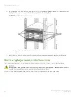
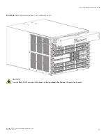
Page 62: ...ice door in this guide Removing logo bezel protective cover The chassis ships with a protective cover installed over the logo bezel and air vents at the top of the port side of the chassis CAUTION Rem...

Page 63: ...over from Brocade X6 4 CAUTION Do not attempt to lift or support the chassis by the logo bezel attached over the port side air vents Removing logo bezel protective cover Brocade X6 4 Director Hardware...

Page 64: ...Brocade X6 4 Director Hardware Installation Guide 64 53 1004106 07...

Page 65: ...nd verification tasks Task Task details or additional information Establish a serial connection to the director Connect a serial cable to the console port on active CP blade and use a terminal emulato...

Page 66: ...nnector An RJ 45 to DB 9 adapter Three Ethernet cables including one spare Access to an FTP server or USB device for backing up uploading or downloading the device configuration or collecting supports...

Page 67: ...ssis with maximum supported blades and optics two power supplies connected to 200 240 VAC are required for full N N redundancy For details on power supplies required for operation and high availabilit...

Page 68: ...you will attach these unterminated wires to your site s DC power terminal blocks For more information on the HVAC HVDC power cord available for these power supplies refer to Using HVAC HVDC power cord...

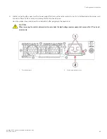
Page 69: ...torx head screws Save the retainer cover and screws for reinstallation after plugging in the power cord CAUTION When removing the metal cable restraint cover under the high voltage power supply inlet...

Page 70: ...ch when the power cord connector is fully inserted into the power supply 1 Power cable 2 Connector latch 8 Attach the cable restraint cover under the power cord connector using its two torx head screw...

Page 71: ...vailability refer to Power supply requirements and Power consumption tables in the Brocade X6 Directors Technical Specifications on page 225 DANGER High Touch Current Earth connection essential before...

Page 72: ...he bottom fan assembly near the bottom of the chassis Using HVAC HVDC power cords HVAC HVDC power supply power cords available from Brocade are shipped with an Anderson Saf D Grid 400 connector on the...

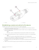
Page 73: ...and for service purposes 3 Use the serial cable provided with the device to connect the console serial port on the active CP to a computer workstation NOTE The active CP is indicated by an illuminated...

Page 74: ...are prompted to change the device passwords Please change passwords for switch default accounts now Use Control C to exit or press Enter key to proceed 8 Press Enter to step through a procedure to cha...

Page 75: ...e active CP is indicated by an illuminated blue LED on the blade front panel If you are already logged through a console port you can determine whether you are logged into the active or standby CP by...

Page 76: ...tion to configure the IP addresses for the device you can connect the active CP blade to the local area network LAN NOTE Connecting the CP blades to a private network or VLAN is recommended After esta...

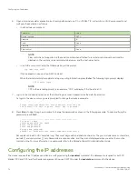
Page 77: ...tially Enter a new value or press Enter to accept each default value c Enter y after the Fabric param prompt Fabric param yes y no n no y d Enter a unique domain ID such as the domain ID used by the p...

Page 78: ...C 2016 switch admin Setting the time zone The default time zone is Coordinated Universal Time UTC The time zone needs to be set only once because the value is stored in nonvolatile memory Use the foll...

Page 79: ...er tsTimeZone 8 0 For Central Standard Time enter tsTimeZone 6 0 For Eastern Standard Time enter tsTimeZone 5 0 TABLE 14 Example tsTimeZone command parameter selection for the US time zones Local time...

Page 80: ...the name causes a domain address format RSCN to be issued 1 Log into the device using one of the following methods A serial console connection to the active CP blade The active CP is indicated by an...

Page 81: ...ps to verify correct operation of the device 1 Check the LEDs of all power supplies fans and blades to verify that all are functional 2 Log into the device using one of the following methods A serial...

Page 82: ...ing admin as your password If you have not changed the default password usepassword 3 Back up the device configuration using the configUpload command Follow the prompts to upload the configuration to...

Page 83: ...ystem is going down for system halt NOW NOTE If you do not use the sysshutdown command and you sequence power off on power distribution units PDU with a few seconds between power offs be aware that a...

Page 84: ...CAUTION When removing the metal cable restraint cover under the high voltage power supply inlet remove the two Torx head screws only b Disconnect the power cable from the power supply Note that the l...

Page 85: ...1 Power cable 2 Connector latch Powering down the chassis Brocade X6 4 Director Hardware Installation Guide 53 1004106 07 85...

Page 86: ...Brocade X6 4 Director Hardware Installation Guide 86 53 1004106 07...

Page 87: ...SWL LWL ELWL Auto negotiate 4 8 16 10 Gbps SFP SWL LWL Fixed 10 10 GbE SFP SR LR USR Fixed 10 10GBase ZRD tunable SFP Fixed 10 1 GbE SFP Copper Fixed 1 1 GbE SX SFP LX SFP and CWDM SFP Fixed 1 40 GbE...

Page 88: ...odule Resources These resources include transceiver data sheets Port and extension blade transceivers FC SFP transceivers installed in port blades and extension blade ports provide connections to devi...

Page 89: ...ptic cable 2 Bail 3 Transceiver Core routing blades QSFPs installed in core routing blades are used for connecting inter switch links ICLs between Brocade X6 Directors or between Brocade X6 and DCX 85...

Page 90: ...fter the addition or removal of a license the license enforcement is performed on the ports only when the portdisable and portenable commands are issued on the ports An ICL license must be installed o...

Page 91: ...s between Brocade X6 and DCX 8510 Directors Brocade 2 km LWL QSFPs All 16 ICL ports can be used for 2km distances when we configure 20 buffer credits are configured per virtual channel The Brocade 2 k...

Page 92: ...traction tool and holster The extraction tool is designed to remove transceivers from modules where the space is limited FIGURE 36 Optical transceiver extraction tool Precautions specific to transceiv...

Page 93: ...ace required for cable management before installing the switch Leave at least 1 m 3 28 ft of slack for each port cable This provides room to remove and replace the switch allows for inadvertent moveme...

Page 94: ...n unqualified transceiver the switchshow command output shows the port in a Mod_Inv state Fabric OS also logs the issue in the system error log To insert an SFP transceiver complete the following step...

Page 95: ...ade port 1 Pull tab 2 Transceiver If transceiver has a bail latch mechanism 10 GbE transceivers ensure that the bail wire handle is in the unlocked position grasp the transceiver and push it into the...

Page 96: ...ed cable intended for an other type of transceiver into a regular SFP transceiver You may damage the cable as well as the transceiver Replacing an SFP transceiver Complete the following steps to remov...

Page 97: ...tical transceiver with pull tab into blade port 1 Pull tab 2 Transceiver If transceiver has a bail latch mechanism 10 GbE transceivers unlatch from the port by pulling the bail wire handle away from i...

Page 98: ...he transceiver until the latching mechanism clicks Cables are keyed so that they can be inserted in only one way If a cable does not slide in easily ensure that it is correctly oriented Installing a Q...

Page 99: ...ed cable you will not need to install a cable The port LED displays steady amber until both ends of the cable are inserted and the link is established When the link is fully established the LED displa...

Page 100: ...he pull tab near the body of the transceiver to reduce the chances of bending the pull tab As the transceiver may be hot always use the pull tab and avoid touching the transceiver body 3 To insert the...

Page 101: ...s not slide in easily ensure that it is correctly oriented 5 Organize cables to avoid covering LEDs and air vents Refer to Cable management on page 93 Verifying the operation of new transceivers You c...

Page 102: ...Brocade X6 4 Director Hardware Installation Guide 102 53 1004106 07...

Page 103: ...tenance This section provides information about determining the status of each component using LEDs and CLI commands Refer to the Brocade Web Tools Administration Guide and the Brocade Fabric OS Admin...

Page 104: ...seconds for polling to complete Connected device is configured in an offline state Verify the status of the connected device Steady green Port is online connected to an external device but has no traf...

Page 105: ...ade is firmly seated with ejectors pushed in fully to center of blade and captive screw for each ejector fully tightened Status No light LED is off Blade is either healthy or does not have power Verif...

Page 106: ...No action required Flickering green Port is online with traffic flowing through port No action required Steady amber Port is receiving light or signal carrier but it is not online yet Reset the port...

Page 107: ...than 5 seconds the CP blade is faulty Ensure that the blade is firmly seated and the switch has completed booting If LED remains amber consult the device supplier Slow flashing amber on 2 seconds the...

Page 108: ...thernet link speed enter the ifModeSet command LED is on Ethernet link speed is 100 1000 Mb s Ethernet link is healthy and traffic is flowing through port No action required Ethernet link activity 10...

Page 109: ...s LED No light LED is off No QSFP module all four QSFP ports are disabled No action needed if the QSFP is not installed or verify that the QSFP is fully inserted Steady amber QSFP module is in all fou...

Page 110: ...er source Steady green Card is receiving power No action required Status No light LED is off Card is either healthy or does not have power No action required Steady amber Card is faulty Replace card I...

Page 111: ...ower cable from power supply remove and reinsert power supply and then reconnect power cable to restart If status persists replace power supply assembly Steady green Power supply has incoming power an...

Page 112: ...cable to restart If status persists replace power supply assembly If status persists replace power supply TABLE 22 HVAC HVDC Power supply LED descriptions LED purpose Color Status Recommended action P...

Page 113: ...er Steady green Fan assembly has power No action required Status No light LED is off Fan assembly is either healthy or does not have power Ensure that the fan assembly has power Steady amber Fan assem...

Page 114: ...information about turning beaconing on or off refer to the Brocade Fabric OS Administration Guide Verify that the switch prompt displays when POST completes If it does not display POST was not succes...

Page 115: ...r supplied information can also be viewed if included for each FRU type Four measurements to note are Power Consume Factor Maximum power allocated for a given FRU Except for power supply assemblies al...

Page 116: ...3 Year 2016 Time Alive 87 days Time Awake 0 days ID CORE BLADE Slot 5 Header Version 2 Power Consume Factor 450W Power Usage 264W Factory Part Num 60 1003199 08 Factory Serial Num DYH0344L005 Manufac...

Page 117: ...h 10 Year 15 Update Day 16 Month 2 Year 2016 Time Alive 88 days Time Awake 3 days ID FAN Unit 2 Fan Direction Non portside Intake Header Version 2 Power Consume Factor 300w Factory Part Num 60 1003203...

Page 118: ...48 27 SULB 1002 95 SLOT 1 CHASSIS INFO My_Chassis Firmwaredownload command has completed successfully 2016 03 28 08 50 51 IPAD 1003 96 SLOT 1 CHASSIS INFO My_Chassis DNS parameters saved successfully...

Page 119: ...003324 01 Factory Serial Number DZD0331L004 POWER SUPPLY Unit 1 Inserted at Fri Jun 17 12 05 26 2016 Factory Part Number 23 0000162 01 Factory Serial Number DUD2M36L04N POWER SUPPLY Unit 2 Inserted at...

Page 120: ...included Temperatures are in Celsius only The following is an example of sensorShow output chassisX6 4 admin sensorshow sensor 1 Temperature is Ok value is 29 C sensor 2 Temperature is Ok value is 47...

Page 121: ...48 DISABLED 8 AP BLADE 186 SX6 ENABLED sfpShow Use this command without operands to display a summary of all installed SFPs For each port the command displays the SFP type and for serial ID SFP the ve...

Page 122: ...5 Slot 7 Port 0 Slot 7 Port 1 Slot 7 Port 2 Slot 7 Port 3 Slot 7 Port 4 Slot 7 Port 5 Slot 7 Port 6 Slot 7 Port 7 Slot 7 Port 8 Slot 7 Port 9 Slot 7 Port 10 Slot 7 Port 11 Slot 7 Port 12 Slot 7 Port 1...

Page 123: ...ort 21 Slot 8 Port 22 Slot 8 Port 23 Slot 8 Port 24 Slot 8 Port 25 Slot 8 Port 26 Slot 8 Port 27 Slot 8 Port 28 Slot 8 Port 29 Slot 8 Port 30 Slot 8 Port 31 Slot 8 Port 32 id sw Vendor BROCADE Serial...

Page 124: ...rt 31 id 7 3 sw Vendor BROCADE Serial No ZTA11539000002A Speed 32_Gbps Slot 6 Port 16 Slot 6 Port 17 Slot 6 Port 18 Slot 6 Port 19 Slot 6 Port 20 Slot 6 Port 21 Slot 6 Port 22 Slot 6 Port 23 Slot 6 Po...

Page 125: ...ne FC F Port 21 00 00 24 ff 90 55 9e 71 4 7 014700 id N32 Online FC F Port 21 00 00 24 ff 90 55 9f 72 4 8 014800 id N32 Online FC E Port 10 00 00 27 f8 f2 c5 b8 73 4 9 014900 id N32 Online FC E Port 1...

Page 126: ...switch ras010 module AGDUMP Saving support information for switch ras010 module AGWWNS Saving support information for switch ras010 module AGWWN_CFG Saving support information for switch ras010 module...

Page 127: ...support information for switch ras010 module FCIP Saving support information for switch ras010 module FCIP_DPLOGS Saving support information for switch ras010 module VFABRIC Saving support information...

Page 128: ...ted during POST are sent to the error logs and to the serial console if connected Diagnostic tests can also be run manually to test and troubleshoot the hardware and the firmware including internal co...

Page 129: ...ric OS Administration Guide and the Brocade Fabric OS Command Reference For information about system error messages errShow or errDump refer to the Fabric OS Troubleshooting and Diagnostics Guide Runn...

Page 130: ...Brocade X6 4 Director Hardware Installation Guide 130 53 1004106 07...

Page 131: ...talled in slots 5 and 6 Up to four hot swappable port blades can be installed in a single chassis to provide up to 192 32 Gbps FC ports The following optics can be installed in the blade s FC ports 32...

Page 132: ...Channel and IP fabrics Brocade Extension supports applications such as remote data replication RDR centralized backup and data migration over very long distances that are impractical or very costly u...

Page 133: ...ce of extension over IP networks including WAN Optimized TCP WO TCP 9K jumbo frame and end to end Path MTU auto discovery Hardware based IPsec supports mix of secure and non secure tunnels on the same...

Page 134: ...ttings Trunk groups must be created between Brocade switches or Brocade adapters in the case of F_Port trunking Brocade trunking is proprietary and is not supported on M EOS or third party switches Th...

Page 135: ...command does not show that the blade is enabled errShow Displays error log messages one at a time Any of the following messages display in the error log or show command output Slot unknown message rel...

Page 136: ...perform the following steps a Delete all fciptunnel configurations using the portcfg fciptunnel slot vePort delete command b Delete all IP Routes defined on the blade to be removed using the portcfg i...

Page 137: ...de 13 If the blade is not being replaced by another blade install a filler panel and reinstall the chassis door The filler panel is required for proper chassis cooling The door is required to meet EMI...

Page 138: ...lade power LEDs illuminate NOTE Be sure that captive screws are tightened If not high pressure from fan operation may unseat blade from chassis connectors 5 Observe the blade power and status LEDs and...

Page 139: ...Displays temperature reading of blades with fan and power supply status errDump Displays the entire system error log errShow Displays error log messages one at a time For output examples and additiona...

Page 140: ...Brocade X6 4 Director Hardware Installation Guide 140 53 1004106 07...

Page 141: ...core routing blade is compatible only with the Brocade X6 4 Core routing blades contain the following LED indicators Green blade power LED Amber blade status LED Bicolor green amber QSFP port status...

Page 142: ...t ASIC within each core blade an ICL trunk cannot be formed using the individual FC ports within the same QSFP A trunk has to be formed from individual FC ports in different QSFP ports These QSFP port...

Page 143: ...n core blades are recommended Following are the maximum numbers of directors that you can connect using 4x32 Gbps quad SFP QSFP inter chassis links ICLs Up to nine X6 GEN6 directors can be connected i...

Page 144: ...low the parallel example shown in the previous figure Each line in the example actually represents four cables running between the devices FIGURE 56 Brocade X6 Director core edge ICL topology Brocade...

Page 145: ...ot or pull the blade from a slot using the ejector handles Faulty core routing blade indicators Confirm that you need to replace the blade before continuing The following events may indicate that a co...

Page 146: ...me while chassis power is on You must replace a blade and ensure its operation before replacing the other core routing blade Removing both blades will shut down the chassis To replace both blades at t...

Page 147: ...status LEDs on the front of each blade to identify any possible problems 3 Before replacing a blade establish a Telnet or console connection to determine a failure and verify operation after replaceme...

Page 148: ...t being replaced by another blade install a filler panel and reinstall the chassis door The filler panel is required for proper chassis cooling The door is required to meet EMI compliance Installing a...

Page 149: ...captive screws are tightened If not high pressure from fan operation may unseat blade from chassis connectors 5 Observe the blade power and status LEDs and verify the following a Verify that the stat...

Page 150: ...y status chassisShow Displays information about each component in the system errDump Displays the entire system error log errShow Displays error log messages one at a time For output examples and addi...

Page 151: ...000Base T RJ45 Ethernet port for service This is an auto sensing MDI port 10 Gbps Base T RJ45 Ethernet port reserved for future use The two 10 100 1000 Mbps Ethernet ports are bound together as a sing...

Page 152: ...Wear an appropriately grounded ESD wrist strap when handling and installing blades and cards Follow electrostatic discharge ESD precautions Wear a wrist grounding strap connected to chassis ground if...

Page 153: ...on The CP blade does not respond to Telnet commands or the serial console is not available The haShow command indicates an error The clock is inaccurate or the CP blade does not boot up or shut down n...

Page 154: ...by following all steps under Completing the replacement on page 164 6 Verify operation of replacement blade by following steps under Verifying blade operation on page 165 7 Repeat preceding steps to r...

Page 155: ...sure to upload the configuration using the map option for a FICON enabled device if port bound addressing is used For more information refer to the Brocade Fabric OS Command Reference 2 Connect to th...

Page 156: ...ce CP blades after removing power to the device Hot swap procedure Use this procedure to replace CP blades one at a time while the device power is on The device continues to operate while replacing a...

Page 157: ...ise This is normal and is due to the dense backplane The blade will move out approximately 1 27 cm 5 in from the slot when fully disengaged 8 Pull the blade out from the slot slightly using the ejecto...

Page 158: ...ckplane connectors c Continue pushing with your thumbs or fingers until the ejectors move in towards the blade slightly indicating that the connectors are engaged d Simultaneously push both ejector ha...

Page 159: ...Bring the replacement blade firmware to the same firmware level as the active blade using one of the following procedures Run the firmwaresync command on the active CP blade to copy all firmware from...

Page 160: ...3 2016 Doing firmwarecommit now Please wait Fri Jun 17 14 55 27 2016 Firmware commit completes successfully Validating the filesystem Fri Jun 17 22 36 05 2016 Doing firmwarecommit now Please wait Fri...

Page 161: ...Broadcast message from root ttyS0 Fri Jun 17 14 49 45 2016 The system is going down for reboot NOW INIT Switching to runlevel 6 INIT Sending processes the TERM signal Chassis_1 admin HAMu Heartbeat do...

Page 162: ...crews will pop out from the slot 63 cm 25 in when fully disengaged Do not eject the blade using blade handles until screws disengage from slot and the power LED is off 6 Grasp both ejector handles and...

Page 163: ...se steps to insert each blade into the slot a Align the blade in the slot with the flat metal side of the blade at the bottom blade power and status LEDs are on the left b Carefully push the blade int...

Page 164: ...device becomes fully functional with the new CP blades 14 Verify that each blade s power LED is green If not ensure that the CP blade has power and is firmly seated and that the ejectors are in the l...

Page 165: ...the faulty CP blade in the packaging provided with the new CP blade and contact the switch supplier to determine the return procedure Verifying blade operation Perform the following tasks to verify o...

Page 166: ...Brocade X6 4 Director Hardware Installation Guide 166 53 1004106 07...

Page 167: ...inserted to compare the critical data If a data mismatch is detected during the audit messages in the RASlog will provide a summary of all errors detected and prompt you through a data recovery proces...

Page 168: ...one WWN card but will be in degraded condition If you have removed a card be sure to replace as soon as possible NOTE Do not use steps in the WWN card and WWN card bezel removal procedures to disable...

Page 169: ...N card Error messages regarding WWN units in chassisshow output Error messages that may indicate problems with a WWN card are summarized in the following table TABLE 25 Messages that may indicate WWN...

Page 170: ...ow direction on WWN cards on page 177 4 Verify WWN card operation using steps under Verifying WWN card operation on page 178 Replacing WWN cards cold swap Use this procedure to replace WWN cards with...

Page 171: ...cation audit will be run to detect any mismatches or other problems A second WWN card is enabled and the WWN card audit will be run If an error is detected during the audit EM 1220 and EM 1222 message...

Page 172: ...2 System AirFlow Non portside Intake Header Version 2 Power Consume Factor 1W Factory Part Num 60 1003194 02 Factory Serial Num DZH0331L032 Manufacture Day 3 Month 10 Year 15 Update Day 0 Month 0 Year...

Page 173: ...e a Phillips screwdriver to tighten the captive screw and secure the card assembly to the chassis NOTE Be sure that captive screws are tightened If not high pressure from fan operation may unseat card...

Page 174: ...on the new cards using the ipaddrset command 1 Unpack the replacement WWN card assembly and save the packaging for the faulty WWN card s The WWN card assemblies are labeled 1 for the left slot and 2...

Page 175: ...perating problems 9 Determine the active CP blade by entering the haShow command 10 On the active CP blade run the wwnrecover command and specify WWN 2 card for recovery when prompted in wwnrecover ou...

Page 176: ...sis and set it aside The ends of both WWN card assemblies with pull tabs are now visible 2 Unscrew the captive screw for the WWN card assembly using a Phillips screwdriver until the assembly releases...

Page 177: ...figuring system airflow direction to Non portside Intake If airflow direction for power supply and fan assemblies does not match WWN cards will not automatically reconfigure and the fan or power suppl...

Page 178: ...fan to both WWN cards Enter Selection 1 WWN Airflow direction recovery complete Please reboot the system 4 Reboot the system Verifying WWN card operation Perform the following tasks to verify operati...

Page 179: ...of the same type and match the airflow of installed fan assemblies Power supply model supporting nonport side air intake NPI provides 1450 W 100 120 VAC and 2870 W 200 240 VAC This assembly has two fa...

Page 180: ...C output power required for device operation Each HVAC HVDC power supply assembly provides the following power outputs in Watts at the indicated AC and DC input rated voltages 1450 W 100 120 VAC 2870...

Page 181: ...ithout special tools If you are replacing one power supply in a configuration with N 1 or greater redundancy the director can continue operating during the replacement if procedures in this guide are...

Page 182: ...or NPE If a mismatched power source or fan assembly is installed by mistake a RASlog message occurs indicating that a mismatch in fan or power supply airflow has occurred and the FRU is faulted NOTE...

Page 183: ...not match the FRU will fault Faulty fans can cause increase in temperature Airflow direction can be verified by entering the chassisShow command Following is an example from command output indicating...

Page 184: ...f the following methods to determine if a power supply is faulty Check the power supply status LED The LED may take up to 10 seconds to illuminate If LED does not illuminate the power supply has no in...

Page 185: ...t system power which could cause some blades to power down Ensure that there is an adequate number of active power supply assemblies when removing a single power unit during hot swap Refer to Power su...

Page 186: ...ower demand can be met 2 Perform one of the following steps If you need to power down the chassis to remove a power supply enter the sysShutdown command Refer to Powering down the chassis on page 83 f...

Page 187: ...panel from the chassis slot 2 Grasp the handle and slide the new power supply into the chassis while supporting the power supply from beneath Push the power supply into slot until the connectors seat...

Page 188: ...erly seated or being turned off psShow Displays the status of each power supply as OK Absent or Faulty If a power supply displays absent or faulty contact the device supplier to order replacement part...

Page 189: ...ns can be installed All fan assemblies must have the same airflow direction and match airflow direction of installed power supplies Fan assembly with nonport side air intake Fans move air from the non...

Page 190: ...y does not match the chassis airflow direction the fan LED will indicate a fault condition Power supply and fan assemblies are labeled with a green E or orange I airflow symbol All fans and power supp...

Page 191: ...Non portside Exhaust WWN Unit 2 System AirFlow Non portside Exhaust NOTE Ensure that captive screws securing the fan and power supply assemblies are tightened If they are not air pressure inside chass...

Page 192: ...f fan assembly displays absent or faulty check if assembly is seated in chassis If it is power supply could be faulty or is not receiving power for some reason Enter sensorShow to determine if a fan i...

Page 193: ...led fan assembly complete the following steps 1 Shut down the system using the sysShutdown command 2 Unplug power cords from receptacles on all power supply assemblies 3 Remove faulty fan assembly 4 I...

Page 194: ...the handle and pull sliding the fan assembly from the chassis while supporting the fan assembly from beneath as you remove it FIGURE 72 Removing and installing a fan assembly 5 If leaving power on fo...

Page 195: ...nShow Displays the status for each fan assembly as OK Absent or Faulty The RPM of each fan in the assembly is also provided If a fan assembly displays absent or faulty contact the chassis supplier to...

Page 196: ...Brocade X6 4 Director Hardware Installation Guide 196 53 1004106 07...

Page 197: ...place If you run the chassis with an uncovered slot the system will overheat Blade filler panels have a latch mechanism at each end of the panel Both latches must be opened to remove and install the p...

Page 198: ...elease Installing a filler panel 1 Pull out the spring loaded latch release on the latch at each end of the cover using your thumb and forefinger and slide the latches toward the center of the cover 2...

Page 199: ...ends pushing the cover firmly into the slot then latching both ends again NOTE Be sure filler panels are securely latched If not high pressure from fan operation may unseat blade from chassis connect...

Page 200: ...Brocade X6 4 Director Hardware Installation Guide 200 53 1004106 07...

Page 201: ...fingers Due to the horizontal orientation of the blades in the device the finger assemblies are attached to the uprights of the mounting rack Time and items required for removal and replacement The re...

Page 202: ...around the assembly 2 Unscrew and save the three 3 screws holding the finger assembly to the rack upright Support the assembly to prevent it from falling 3 Remove the cable management finger assembly...

Page 203: ...rack upright Cable management fingers are shown installed in following illustration FIGURE 76 Cable management finger assemblies 1 Cable management finger assemblies 2 Arrange the cables along the ca...

Page 204: ...Brocade X6 4 Director Hardware Installation Guide 204 53 1004106 07...

Page 205: ...and items required The first time installation procedure for the chassis door takes 15 minutes or longer because you must remove the logo bezel and install ball studs to mount the door Thereafter rem...

Page 206: ...cement of the chassis door Installing a chassis door Complete the following steps to install the door on the port side of the chassis Installing a chassis door Brocade X6 4 Director Hardware Installat...

Page 207: ...ips screwdriver b While supporting the bezel use a Phillips screwdriver to remove the 6 32 X 1 4 in flathead Phillips screws securing each end of the bezel to the chassis and remove bezel c Remove the...

Page 208: ...the chassis air vent and three ball studs into the holes located below the blades at the bottom of the chassis Screw ball studs in finger tight NOTE The ball studs are packaged with the chassis in th...

Page 209: ...in the back of door with the six ball studs in the chassis and push the door into place It will snap onto the studs FIGURE 80 Installing chassis door Installing a chassis door Brocade X6 4 Director Ha...

Page 210: ...Brocade X6 4 Director Hardware Installation Guide 210 53 1004106 07...

Page 211: ...peration and configuration NOTE New WWN cards are shipped preinstalled in the replacement chassis Do not replace the WWN cards in the replacement chassis with the old WWN cards from chassis that you a...

Page 212: ...ing correct operation of system on page 221 9 Verifying correct operation of system on page 221 Chassis fault indicators Verify that replacement of the chassis is necessary If error messages and LED o...

Page 213: ...chassis 1 and 2 Phillips screwdriver Use 1 Phillips screwdriver for removing and installing blades and FRUs in chassis Preparing for replacement Before beginning replacement procedures you must run t...

Page 214: ...on information Location of config switch txt file Location of config miscinfo txt file IP address subnet mask WWN for the device SAN profile Location of SANbefor txt file Notes regarding nsshow output...

Page 215: ...0 0 Host Name cp0 Gateway IP Address 10 33 48 1 CP1 Ethernet IP Address 10 33 60 87 Ethernet Subnetmask 255 255 240 0 Host Name cp1 Gateway IP Address 10 33 48 1 Backplane IP address of CP0 10 0 0 5 B...

Page 216: ...eSzRScycazfT0G Trunking license RyeSzRScycS0fT09 4 Domain Fabric license 8 Enter supportShow then copy the command output into a text file named spptshow txt NOTE The supportShow command has a very lo...

Page 217: ...ide Transceivers without integrated cables can be left in the blades or removed 6 Disconnect all cables from the CP blades Removing components from the chassis Follow electrostatic discharge ESD preca...

Page 218: ...cle the packaging b Open the top of the shipping box and remove accessory kit rack mount kits and foam from the top of the chassis c Lift the cardboard shipping container and inner cardboard sleeve of...

Page 219: ...s to power on device Refer to Providing power to the device on page 66 The device performs a power on self test POST The POST takes a minimum of three minutes and is complete when LED activity returns...

Page 220: ...e as admin switch admin login login admin password xxxxxxxx switch admin NOTE If you are using the Virtual Fabric feature you must run configdownload vf before running the configdownload command to re...

Page 221: ...password xxxxxxxx switch admin 2 Enter the chassisShow command to verify that airflow direction set on WWN cards matches airflow direction for fans in fan and power supply assemblies installed in devi...

Page 222: ...s Mode 0 Index Slot Port Address Media Speed State Proto 64 4 0 014000 N32 Online FC F Port 10 00 00 05 1e f8 a0 b4 65 4 1 014100 N32 Online FC F Port 10 00 00 05 33 26 0e 65 66 4 2 014200 N32 Online...

Page 223: ...FID 1 1 1 1 1 128 128 128 128 128 output truncated switch admin 2 Determine any differences between the information in the SANafter txt file and the information in the SANbefor txt file created earli...

Page 224: ...Brocade X6 4 Director Hardware Installation Guide 224 53 1004106 07...

Page 225: ...chassis 384 ports with 32 Gbps data rate plus 32 4x32 Gbps ICLs ISL trunking Can use up to 8 ports in a trunk group to form a 256 Gbps trunk UltraScale ICL bandwidth Brocade X6 4 Director 2 Tbps 16 U...

Page 226: ...rol Data traffic types Fabric switches supporting unicast multicast 255 groups and broadcast Media types FC32 48 port blade supports Brocade hot pluggable 32 Gbps SWL LWL SFP28 16 Gbps SWL LWL ELWL SF...

Page 227: ...sed on activity and status of all four lanes Bicolor green and amber Fibre Channel port status on extension blades displaying eight different LED states based on port activity and status Bicolor green...

Page 228: ...kg 54 lb 68 95 kg 152 0 lb Weight includes all blades and two power supplies Brocade X6 4 Director with Airflow Diverter and Port Side Exhaust Kit 40 00 cm 15 75 inches 43 74 cm 17 22 inches 61 29 cm...

Page 229: ...t Scale 1 12 Grms Air flow Brocade X6 8 Maximum 1711 cmh 1007 cfm Brocade X6 8 Nominal 985 cmh 580 cfm Brocade X6 4 Maximum 953 cmh 561 cfm Brocade X6 4 Nominal 486 cmh 286 cfm N A Heat dissipation Br...

Page 230: ...utput redundancy in case of single power supply failure Although examples for different port and blade configurations are provided for more information and help with determining the actual number of p...

Page 231: ...tem power but two must be installed to provide power efficiency and redundancy Brocade X6 4 fully loaded 2 CP blades 2 CR blades 4 FC32 48 port blades 2 fan assemblies Brocade X6 8 2647 W 9034 BTU hr...

Page 232: ...C high line 200 240 VAC One power supply provides system power but two must be installed to provide power efficiency and redundancy Brocade X6 4 fully loaded 2 CP blades 2 CR blades 4 FC32 48 port bla...

Page 233: ...00 VDC 2 power supplies for AC low line 100 120 VAC 1 power supply for AC high line 200 277 VAC One power supply provides system power but two must be installed to provide power efficiency and redunda...

Page 234: ...ades 2 CR blades 8 FC32 48 port blades 3 fan assemblies Power consumption modules For blades in the following table Idle blade enabled chips initialized no optics ports disabled Nominal blade enabled...

Page 235: ...2 300 m 984 ft OM3 550 m 1 804 ft OM4 N A N A 62 5 33 m 108 ft N A N A 9 N A 10 km 6 2 miles N A 16 50 35 m 115 ft OM2 100 m 328 ft OM3 125 m 410 ft OM4 N A N A 62 5 15 m 49 ft N A N A 9 N A 10 km 6 2...

Page 236: ...al Description 1 Not supported NA 2 Not supported NA 3 UART1_RXD Transmit data 4 GND Logic ground 5 GND Logic ground 6 UART1_TXD Receive data 7 Not supported NA 8 Not supported NA Serial port specific...

Page 237: ...aste electrical and electronic equipment EU WEEE 94 62 EC packaging and packaging waste EU 2006 66 EC batteries and accumulators and waste batteries and accumulators EU battery directive 1907 2006 of...

Page 238: ...Brocade X6 4 Director Hardware Installation Guide 238 53 1004106 07...

Page 239: ...003 Class A Cet appareil num rique de la classe A est conforme la norme NMB 003 du Canada CE statement ATTENTION This is a Class A product In a domestic environment this product might cause radio inte...

Page 240: ...ect the interference at the user s own expense KCC statement Republic of Korea Class A device Broadcasting Communication Device for Office Use This device obtained EMC registration for office use Clas...

Page 241: ...indique une d faillance ou une panne de courant v rifiez que le ventilateur est bien log dans le ch ssis et que les vis qui fixent le ventilateur au ch ssis sont bien serr es Si les vis sont desserr e...

Page 242: ...supplies and fan trays are clearly labeled with either a green arrow with an E or an orange arrow with an I VORSICHT Vergewissern Sie sich dass die Luftstromrichtung des Netzteils der eingebauten L f...

Page 243: ...N No intente levantar ni sostener el chasis sujetando el bisel del logotipo colocado sobre las ventilas que se encuentra al lado del puerto Ethernet de la puerta CAUTION Remove the logo bezel protect...

Page 244: ...ispositivo sea conforme a la certificaci n NEBS utilice un cable de conexi n a tierra de calibre AWG 2 como m nimo El cable de conexi n a tierra debe disponer de un conector engarzado homologado sumin...

Page 245: ...d l uft das System hei MISE EN GARDE Si vous n installez pas de module ou de bloc d alimentation dans un slot vous devez laisser le panneau du slot en place Si vous faites fonctionner le ch ssis avec...

Page 246: ...nen Un nonc de danger indique des conditions ou des situations potentiellement mortelles ou extr mement dangereuses Des tiquettes de s curit sont pos es directement sur le produit et vous avertissent...

Page 247: ...e levage hydraulique ou lectrique pour l installation PELIGRO Un chasis con la configuraci n incomplete pesa aproximadamente 24 49 kg 54 libras y requiere un elevador hidr ulico o asistido para realiz...

Page 248: ...tromkabeln in Ihrem Land zust ndig ist Das Siegel ist Ihre Garantie dass das Stromkabel sicher mit Ihrem Ger t verwendet werden kann DANGER Si l installation n cessite un cordon d alimentation autre q...

Page 249: ...s sur la puissance de rayonnement de cat gorie 1 de la FDA d finies au sous chapitre 21 CFR I et les normes IEC 60825 et EN60825 Les produits optiques non conformes ces normes sont susceptibles d mett...

Reviews: