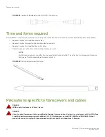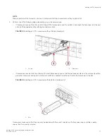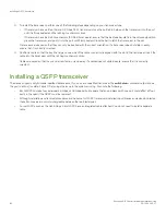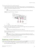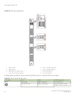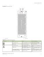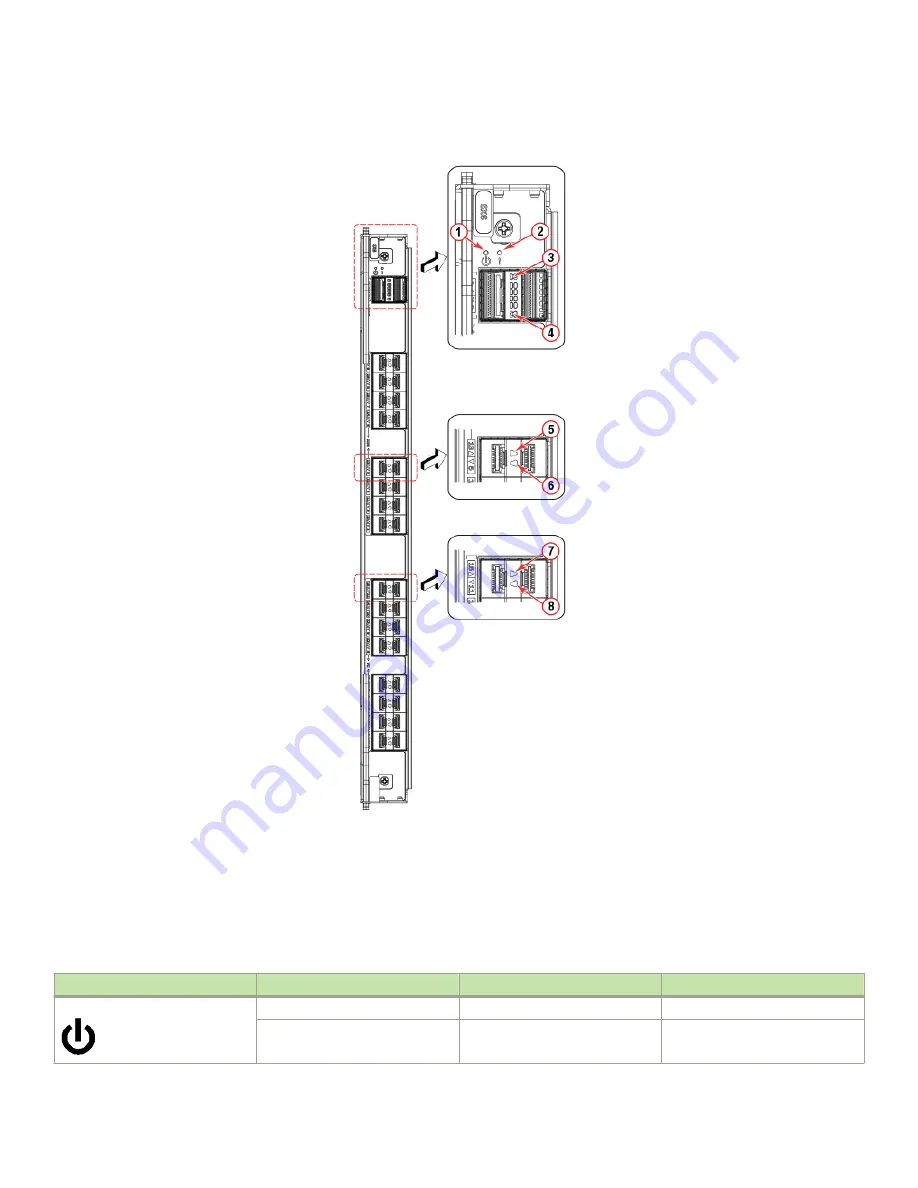
FIGURE 30
SX6 Extension blade LEDs
1.
Blade power LED
2.
Blade status LED
3.
Right 40 GbE QSFP (port 0) status LED
4.
Left 40 GbE QSFP (port 1) status LED
5.
Right 1 or 10 GbE port status LED
6.
Left 1 or 10 GbE port status LED
7.
Right FC port status LED
8.
Left FC port status LED
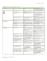
The following table describes the extension blade LED patterns and the recommended actions for those patterns.
TABLE 13
Extension blade LED descriptions
LED purpose
Color
Status
Recommended action
Power
Steady green
Blade is operational.
No action required.
No light (LED is off)
Blade is not powered on.
Ensure that the blade is firmly
seated, with ejectors pushed in fully
Interpreting extension blade LEDs
Brocade X6-8 Director Hardware Installation Guide
88
53-1004105-07
Summary of Contents for X6-8
Page 12: ...Brocade X6 8 Director Hardware Installation Guide 12 53 1004105 07...
Page 20: ...Brocade X6 8 Director Hardware Installation Guide 20 53 1004105 07...
Page 28: ...Brocade X6 8 Director Hardware Installation Guide 28 53 1004105 07...
Page 68: ...Brocade X6 8 Director Hardware Installation Guide 68 53 1004105 07...
Page 84: ...Brocade X6 8 Director Hardware Installation Guide 84 53 1004105 07...
Page 130: ...Brocade X6 8 Director Hardware Installation Guide 130 53 1004105 07...
Page 142: ...Brocade X6 8 Director Hardware Installation Guide 142 53 1004105 07...
Page 160: ...Brocade X6 8 Director Hardware Installation Guide 160 53 1004105 07...
Page 184: ...Brocade X6 8 Director Hardware Installation Guide 184 53 1004105 07...
Page 196: ...Brocade X6 8 Director Hardware Installation Guide 196 53 1004105 07...
Page 230: ...Brocade X6 8 Director Hardware Installation Guide 230 53 1004105 07...

