background image

Interpreting control processor blade LEDs

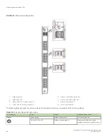
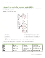
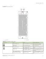
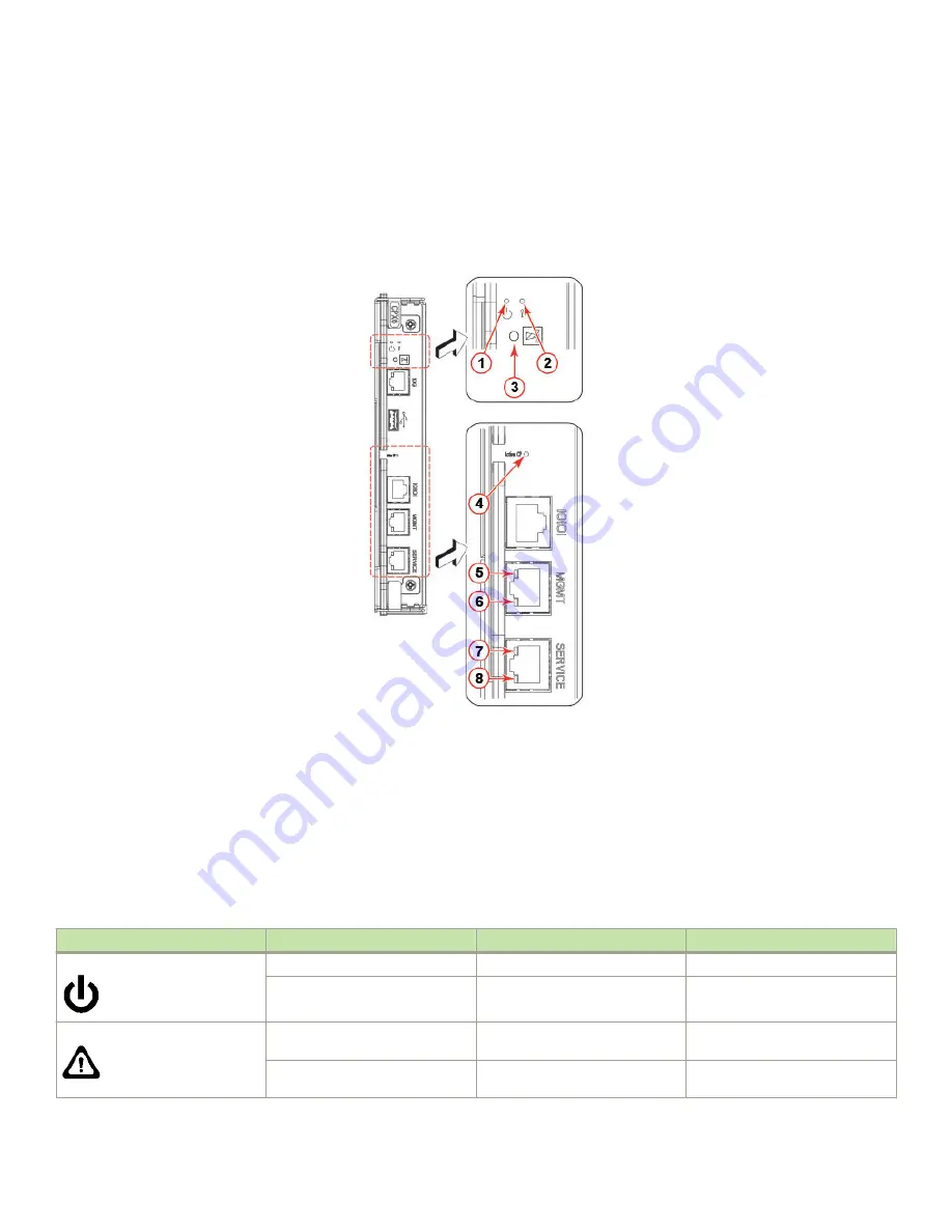
Refer to the following illustration and table to interpret the LED patterns on the CPX6 blade. The LED patterns may temporarily change
during POST and other diagnostic tests.

FIGURE 31 

Control processor blade (CPX6)

1.

Blade power LED

2.

Blade status LED

3.

Chassis beacon LED

4.

Active (blue) CP LED

5.

10/100/1000 Mb/s Ethernet port (MGMT) link status LED

6.

10/100/1000 Mb/s Ethernet port (MGMT) link activity LED

7.

10/100/1000 Mb/s Ethernet port (SERVICE) link status LED

8.

10/100/1000 Mb/s Ethernet port (SERVICE) link activity LED

NOTE

The 10 Gbps Base-T RJ45 Ethernet port, shown below the blade beacon LED, is reserved for future use.

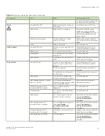
The following table describes the CP blade LED patterns and the recommended actions for those patterns.

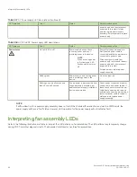
TABLE 14 

CP blade LED descriptions 

LED purpose

Color

Status

Recommended action

Power

Steady green

CP blade is on.

No action required.

No light (LED is off)

CP blade is not on.

Ensure that the blade is firmly
seated and has power.

Attention

No light (LED is off)

CP blade is either healthy or does
not have power.

Verify that the power LED is on.

Steady amber

If on for more than 5 seconds, the
CP blade is faulty.

Ensure that the blade is firmly
seated and the switch has

Interpreting control processor blade LEDs

Brocade X6-8 Director Hardware Installation Guide

90

53-1004105-07

Summary of Contents for X6-8

Page 1: ...HARDWARE INSTALLATION GUIDE Brocade X6 8 Director Hardware Installation Guide 53 1004105 07 12 May 2017...

Page 2: ...ocument describes features that may not be currently available Contact a Brocade sales office for information on feature and product availability Export of technical data contained in this document ma...

Page 3: ...s 21 ESD precautions 22 Power precautions 22 Lifting precautions 22 Laser precautions 23 Facility requirements 23 Time and items required for installation 24 Quick installation checklists 25 Pre insta...

Page 4: ...configuration 64 Powering down the chassis 65 Installing Transceivers and Cables 69 Supported transceivers and cables 69 Port and extension blade transceivers 70 Core routing blades 71 Time and items...

Page 5: ...ade overview 131 CR32 8 port numbering 131 ICL trunking groups 133 ICL cabling configurations 134 Precautions specific to the blade 135 Faulty core routing blade indicators 136 Time and items required...

Page 6: ...Fan and power supply airflow 176 Precautions specific to power supply assembly 178 Power supply assembly fault indicators 178 Power supply assembly task guide 179 Installing additional power supply ho...

Page 7: ...Synchronizing airflow direction on WWN cards 211 Downloading the configuration 212 Reconnecting system to the network and fabric 212 Verifying correct operation of system 213 Verifying correct config...

Page 8: ...statement Taiwan 231 Canadian requirements 231 CE statement 231 China ROHS 232 FCC warning US only 232 KCC statement Republic of Korea 232 VCCI statement 232 Germany statement 232 Cautions and Danger...

Page 9: ...interrupted or the device might reboot CAUTION A Caution statement alerts you to situations that can be potentially hazardous to you or cause damage to hardware firmware software or data DANGER A Dang...

Page 10: ...sources Visit the Brocade website to locate related documentation for your product and additional Brocade resources White papers data sheets and the most recent versions of Brocade software and hardwa...

Page 11: ...Sev 2 High issues Continental US 1 800 752 8061 Europe Middle East Africa and Asia Pacific 800 AT FIBREE 800 28 34 27 33 Toll free numbers are available in many countries For areas unable to access a...

Page 12: ...Brocade X6 8 Director Hardware Installation Guide 12 53 1004105 07...

Page 13: ...C 2870 W 200 277 VAC 2870 W 240 380 VDC This model supports nonport side intake NPI airflow Fabric OS 8 1 0a Yes XBR X6 HVNPEPSU 0104 Dual function high voltage model provides the following power outp...

Page 14: ...206 Revised introduction to using critical information checklist removed note to run supportShow command removed sw option from step to enter ipAddrShow command and added more information to step to...

Page 15: ...oups up to eight ports to create high performance 256 Gbps ISL trunks between switches using 32 Gbps ports Support for FC quad SFP QSFP ports supporting 4x16 Gbps and 4x32 Gbps on core CR blades Up to...

Page 16: ...oltages Redundant primary power connections ensure high availability Each power supply assembly has its own connector so the number of primary power connections is four for optimum efficiency and redu...

Page 17: ...per slot 2 lower NOTE Depending on the fans and power supplies installed airflow can be from the port side to the nonport side of chassis or from the nonport side to the port side of the chassis CAUTI...

Page 18: ...cessor CP core routing CR port and extension blades into slot numbers as follows Slots 1 2 are restricted to CP blades Note that the blade installed in slot 1 will be designated as CP0 while the blade...

Page 19: ...nding on fans and power supplies installed airflow can be from the port side to the nonport side of the chassis or the nonport side to the port side of chassis Although not illustrated the chassis lab...

Page 20: ...Brocade X6 8 Director Hardware Installation Guide 20 53 1004105 07...

Page 21: ...e installation see the precautions in Power precautions CAUTION Changes or modifications made to this device that are not expressly approved by the party responsible for compliance could void the user...

Page 22: ...power sources are intended for installation in restricted access areas only A restricted access area is a location where access can be gained only by trained service personnel through the use of a sp...

Page 23: ...rical rating on the chassis nameplate Location close to the chassis and easily accessible Grounded outlets installed by a licensed electrician and compatible with the power cords Ensure that all equip...

Page 24: ...g 254 lb To find the weight of your device fully populated with the required port blades refer to Brocade X6 Directors Technical Specifications on page 217 Installing rack mount kit 30 minutes Refer t...

Page 25: ...o install Power Supplies if required to install Review the safety precautions Refer to Safety precautions on page 21 Plan the installation Obtain the appropriate rack mount kit Refer to Mounting optio...

Page 26: ...mmand to change the default switch name Use the chassisname command to change the default chassis name Refer to Customizing the chassis and switch name on page 62 for more information Establish an Eth...

Page 27: ...as ordered for installed power supplies Serial cable ESD wrist strap SFP extraction tool Power cord retainer clips Cable management comb assembly 4 GB USB drive China RoHS Hazardous Toxic Substance st...

Page 28: ...Brocade X6 8 Director Hardware Installation Guide 28 53 1004105 07...

Page 29: ...ing the 14U Rack Mount Kit for Four Post Racks XBR DCX 0120 and XBR DCX 0152 on page 31 for instructions In a two post Telco rack Use the 14U mid mount rack kit for two post racks XBR DCX 0121 Refer t...

Page 30: ...weighs approximately 145 83 kg 321 5 lbs and requires a hydraulic or assisted lift to install it 1 Unpack the device a Cut the bands that encircle the packaging b Open the top of the shipping box and...

Page 31: ...supported during the transfer 8 Reinstall the cable management comb if you removed it 9 Reinstall the chassis door The door must be installed to meet EMI compliance Installing the 14U Rack Mount Kit f...

Page 32: ...shelf bracket rail brackets may differ from ones shown in illustration All 1 10 32 x 5 8 in 1 58 cm panhead Phillips screw and washer torque to 32 in lb 37 cm kg All 6 10 32 clip nut For rack rails w...

Page 33: ...that have rails with square holes 8 3 8 in 0 953 cm alignment washer for cabinets that have rails with square holes Parts list NEBS kit The following table lists the parts supplied in the XBR SLX9850...

Page 34: ...tainer 6 Assembling the rack hardware Attach the left and right rack mount shelf brackets to the rack rails NOTE If cables are to be routed down through the cable management comb allow space below the...

Page 35: ...ket 16 total 4 3 8 in 0 953 cm alignment washer for rails with square holes 4 on each end of each bracket 16 total 5 1 4 20 x 1 2 in 1 27 cm panhead Phillips screw with thread locker for rails with sq...

Page 36: ...ighten the screws to a torque of 80 in lb 92 cm kg FIGURE 6 Nut and screw locations for mounting the device 1 10 32 clip nuts for round holes 2 Rail 3 10 32 retainer nut for square holes 4 Rail 5 Top...

Page 37: ...alling the device in the rack Use the following procedure to install the device in the rack DANGER Use safe lifting practices when moving the product 1 Ensure that the door if installed is removed fro...

Page 38: ...s supported during the transfer FIGURE 7 Positioning the device for installation in a rack 1 Rack 2 Nonport side of device Installing the 14U Rack Mount Kit for Four Post Racks XBR DCX 0120 and XBR DC...

Page 39: ...llips screw with washer 7 Reinstall the device door if removed from your device For instructions refer to the door removal and replacement procedures in your device installation guide Installing the 1...

Page 40: ...and Items required Allow approximately one hour to unpack and install a chassis in a rack The following tools are required when installing the 14U Chassis Mid Mount Rack Kit for Two Post Racks Torque...

Page 41: ...type Assembling the rack hardware Perform the following steps to assemble the rack hardware 1 Attach the rear tray with or without adapter as required to both rack rails Orient the tray refer the fol...

Page 42: ...GURE 10 Attaching the rear tray to the rack rails 2 Tray rear mid mount chassis 3 Adapter rear mid mount right 4 Adapter rear mid mount left 5 Screws Installing the 14U Chassis Mid Mount Rack Kit for...

Page 43: ...vice in the rack DANGER Use safe lifting practices when moving the product NOTE A fully populated device requires a hydraulic or assisted lift to install into a rack Installing the 14U Chassis Mid Mou...

Page 44: ...able lock the wheels of the lift 4 Slide the device into the trays until the front edge of the device is seated against the front tray FIGURE 12 Placing the device in the trays 1 Tray front mid mount...

Page 45: ...ll interfere with the screw heads FIGURE 13 Attaching trays to the device 8 Reinstall the device door For instructions refer to the door removal and installation instructions in your device installati...

Page 46: ...shut down Remove this cover by removing the Phillips screws securing it to the mounting bracket on each side of the chassis FIGURE 14 Removing bezel protective cover from Brocade X6 8 CAUTION Do not...

Page 47: ...nd verification tasks Task Task details or additional information Establish a serial connection to the director Connect a serial cable to the console port on active CP blade and use a terminal emulato...

Page 48: ...nnector An RJ 45 to DB 9 adapter Three Ethernet cables including one spare Access to an FTP server or USB device for backing up uploading or downloading the device configuration or collecting supports...

Page 49: ...chassis with maximum supported blades and optics four power supplies connected to 200 240 VAC lines are required for full N N redundancy For details on power supplies required for operation and high a...

Page 50: ...fy how you will attach these unterminated wires to your site s DC power terminal blocks For more information on the HVAC HVDC power cord available for these power supplies refer to Using HVAC HVDC pow...

Page 51: ...torx head screws Save the retainer cover and screws for reinstallation after plugging in the power cord CAUTION When removing the metal cable restraint cover under the high voltage power supply inlet...

Page 52: ...ch when the power cord connector is fully inserted into the power supply 1 Power cable 2 Connector latch 8 Attach the cable restraint cover under the power cord connector using its two torx head screw...

Page 53: ...gh availability refer to Power supply requirements and Power consumption tables in the Brocade X6 Directors Technical Specifications on page 217 DANGER High Touch Current Earth connection essential be...

Page 54: ...e fan assemblies near the bottom of the chassis Using HVAC HVDC power cords HVAC HVDC power supply power cords available from Brocade are shipped with an Anderson Saf D Grid 400 connector on the power...

Page 55: ...and for service purposes 3 Use the serial cable provided with the device to connect the console serial port on the active CP to a computer workstation NOTE The active CP is indicated by an illuminated...

Page 56: ...are prompted to change the device passwords Please change passwords for switch default accounts now Use Control C to exit or press Enter key to proceed 8 Press Enter to step through a procedure to cha...

Page 57: ...e active CP is indicated by an illuminated blue LED on the blade front panel If you are already logged through a console port you can determine whether you are logged into the active or standby CP by...

Page 58: ...tion to configure the IP addresses for the device you can connect the active CP blade to the local area network LAN NOTE Connecting the CP blades to a private network or VLAN is recommended After esta...

Page 59: ...tially Enter a new value or press Enter to accept each default value c Enter y after the Fabric param prompt Fabric param yes y no n no y d Enter a unique domain ID such as the domain ID used by the p...

Page 60: ...C 2016 switch admin Setting the time zone The default time zone is Coordinated Universal Time UTC The time zone needs to be set only once because the value is stored in nonvolatile memory Use the foll...

Page 61: ...er tsTimeZone 8 0 For Central Standard Time enter tsTimeZone 6 0 For Eastern Standard Time enter tsTimeZone 5 0 TABLE 10 Example tsTimeZone command parameter selection for the US time zones Local time...

Page 62: ...the name causes a domain address format RSCN to be issued 1 Log into the device using one of the following methods A serial console connection to the active CP blade The active CP is indicated by an...

Page 63: ...ps to verify correct operation of the device 1 Check the LEDs of all power supplies fans and blades to verify that all are functional 2 Log into the device using one of the following methods A serial...

Page 64: ...ing admin as your password If you have not changed the default password usepassword 3 Back up the device configuration using the configUpload command Follow the prompts to upload the configuration to...

Page 65: ...ystem is going down for system halt NOW NOTE If you do not use the sysshutdown command and you sequence power off on power distribution units PDU with a few seconds between power offs be aware that a...

Page 66: ...CAUTION When removing the metal cable restraint cover under the high voltage power supply inlet remove the two Torx head screws only b Disconnect the power cable from the power supply Note that the l...

Page 67: ...1 Power cable 2 Connector latch Powering down the chassis Brocade X6 8 Director Hardware Installation Guide 53 1004105 07 67...

Page 68: ...Brocade X6 8 Director Hardware Installation Guide 68 53 1004105 07...

Page 69: ...WL LWL ELWL Auto negotiate 4 8 16 10 Gbps SFP SWL LWL Fixed 10 10 GbE SFP SR LR USR Fixed 10 10GBase ZRD tunable SFP Fixed 10 1 GbE SFP Copper Fixed 1 1 GbE SX SFP LX SFP and CWDM SFP Fixed 1 40 GbE Q...

Page 70: ...odule Resources These resources include transceiver data sheets Port and extension blade transceivers FC SFP transceivers installed in port blades and extension blade ports provide connections to devi...

Page 71: ...ptic cable 2 Bail 3 Transceiver Core routing blades QSFPs installed in core routing blades are used for connecting inter switch links ICLs between Brocade X6 Directors or between Brocade X6 and DCX 85...

Page 72: ...fter the addition or removal of a license the license enforcement is performed on the ports only when the portdisable and portenable commands are issued on the ports An ICL license must be installed o...

Page 73: ...s between Brocade X6 and DCX 8510 Directors Brocade 2 km LWL QSFPs All 16 ICL ports can be used for 2km distances when we configure 20 buffer credits are configured per virtual channel The Brocade 2 k...

Page 74: ...traction tool and holster The extraction tool is designed to remove transceivers from modules where the space is limited FIGURE 22 Optical transceiver extraction tool Precautions specific to transceiv...

Page 75: ...l recommendations Plan for rack space required for cable management before installing the switch Leave at least 1 m 3 28 ft of slack for each port cable This provides room to remove and replace the sw...

Page 76: ...n unqualified transceiver the switchshow command output shows the port in a Mod_Inv state Fabric OS also logs the issue in the system error log To insert an SFP transceiver complete the following step...

Page 77: ...ade port 1 Pull tab 2 Transceiver If transceiver has a bail latch mechanism 10 GbE transceivers ensure that the bail wire handle is in the unlocked position grasp the transceiver and push it into the...

Page 78: ...ed cable intended for an other type of transceiver into a regular SFP transceiver You may damage the cable as well as the transceiver Replacing an SFP transceiver Complete the following steps to remov...

Page 79: ...tical transceiver with pull tab into blade port 1 Pull tab 2 Transceiver If transceiver has a bail latch mechanism 10 GbE transceivers unlatch from the port by pulling the bail wire handle away from i...

Page 80: ...he transceiver until the latching mechanism clicks Cables are keyed so that they can be inserted in only one way If a cable does not slide in easily ensure that it is correctly oriented Installing a Q...

Page 81: ...ed cable you will not need to install a cable The port LED displays steady amber until both ends of the cable are inserted and the link is established When the link is fully established the LED displa...

Page 82: ...the pull tab near the body of the transceiver to reduce the chances of bending the pull tab As the transceiver may be hot always use the pull tab and avoid touching the transceiver body 3 To insert th...

Page 83: ...es not slide in easily ensure that it is correctly oriented 5 Organize cables to avoid covering LEDs and air vents Refer to Cable management on page 75 Verifying the operation of new transceivers You...

Page 84: ...Brocade X6 8 Director Hardware Installation Guide 84 53 1004105 07...

Page 85: ...gh reliability high availability and enhanced serviceability RAS and requires no routine operational steps or maintenance This section provides information about determining the status of each compone...

Page 86: ...patterns TABLE 12 Port blade LED descriptions LED purpose Color Status Recommended action Power Steady green Blade is operational No action required No light LED is off Blade is not powered on Ensure...

Page 87: ...w flashing green on 1 second then off 1 second Port is online but segmented indicating a loopback plug or cable or an incompatible switch Verify that the correct device is attached to the chassis Fast...

Page 88: ...The following table describes the extension blade LED patterns and the recommended actions for those patterns TABLE 13 Extension blade LED descriptions LED purpose Color Status Recommended action Pow...

Page 89: ...is in progress Allow 60 seconds for polling to complete Connected device is configured in an offline state Verify the status of the connected device Steady green Port is online connected to an externa...

Page 90: ...10 Gbps Base T RJ45 Ethernet port shown below the blade beacon LED is reserved for future use The following table describes the CP blade LED patterns and the recommended actions for those patterns TA...

Page 91: ...on link Ensure that the blade has power the Ethernet cable is firmly seated and the connected device is functioning Blinking green Activity is present on link No action required Active CP Steady blue...

Page 92: ...green Blade is on No action required No light LED is off Blade is not on Ensure that the blade is firmly seated and has power Status No light LED is off Blade is either healthy or does not have power...

Page 93: ...nking amber Port is disabled or faulted FC link activity segmented loopback mode also during transition between cable plug in and all four ports online Check for console messages or wait for all four...

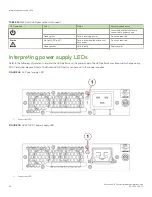
Page 94: ...ady amber Card is faulty Replace card Interpreting power supply LEDs Refer to the following information to interpret the LED patterns on the power supply The LED patterns may temporarily change during...

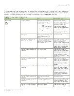
Page 95: ...ut disconnect power cable from power supply remove and reinsert power supply and then reconnect power cable to restart If status persists replace power supply assembly Flashing on two times and then o...

Page 96: ...providing power to the device No action required Flashing on one half second and then off one half second Source power is disconnected from the power supply assembly but additional power supply instal...

Page 97: ...Fan assembly is either healthy or does not have power Ensure that the fan assembly has power Steady amber Fan assembly is being initialized or has a failure full or partial Wait to see if fan fully i...

Page 98: ...POST has completed without error do the following Verify that all LEDs return to a normal state after POST completes If one or more LEDs do not return to a normal state and this is not due to the devi...

Page 99: ...SupportSave For more detail on using these commands refer to the Brocade Fabric OS Command Reference For more information on error messages refer to the Brocade Fabric OS Message Reference chassisShow...

Page 100: ...rsion 2 Power Consume Factor 50W Power Usage 47W Factory Part Num 60 1003201 09 Factory Serial Num DYK0338L008 Manufacture Day 7 Month 10 Year 2015 Update Day 23 Month 3 Year 2016 Time Alive 84 days T...

Page 101: ...ID SW BLADE Slot 9 Header Version 2 Power Consume Factor 245W Power Usage 154W Factory Part Num 60 1003200 07 Factory Serial Num DYJ0332L035 Manufacture Day 26 Month 9 Year 2015 Update Day 15 Month 3...

Page 102: ...Month 2 Year 2016 Time Alive 68 days Time Awake 2 days ID FAN Unit 1 Fan Direction Non portside Intake Header Version 2 Power Consume Factor 300w Factory Part Num 60 1003203 03 Factory Serial Num DYL...

Page 103: ...016 03 28 08 44 28 FV 1001 90 SLOT 1 CHASSIS INFO My_Switch Flow Vision daemon initialized 2016 03 28 08 44 51 FSSM 1002 91 SLOT 1 CHASSIS INFO My_Chassis HA State is in sync 2016 03 28 08 44 51 SULB...

Page 104: ...usually a result of a reboot of the active CP which disrupts traffic A lack of HA synchronization can be related to a firmware download in progress or that the device is recovering from a reboot or po...

Page 105: ...1003200 07 Factory Serial Number DYJ0332L006 WWN Unit 2 Inserted at Mon Jun 13 13 59 14 2016 Factory Part Number 60 1003194 02 Factory Serial Number DZH0331L032 SW BLADE Slot 6 Inserted at Mon Jun 13...

Page 106: ...re is Ok value is 43 C sensor 12 Temperature is Ok value is 46 C sensor 13 Temperature is Ok value is 41 C sensor 14 Temperature is Ok value is 36 C sensor 15 Temperature is Ok value is 38 C sensor 16...

Page 107: ...3 SW BLADE 178 FC32 48 ENABLED 4 SW BLADE 178 FC32 48 ENABLED 5 AP BLADE 186 SX6 ENABLED 6 SW BLADE 178 FC32 48 DISABLED 7 CORE BLADE 176 CR32 8 ENABLED 8 CORE BLADE 176 CR32 8 ENABLED 9 SW BLADE 178...

Page 108: ...Port 0 Slot 6 Port 1 Slot 6 Port 2 Slot 6 Port 3 Slot 6 Port 4 Slot 6 Port 5 Slot 6 Port 6 Slot 6 Port 7 Slot 6 Port 8 Slot 6 Port 9 Slot 6 Port 10 Slot 6 Port 11 Slot 6 Port 12 Slot 6 Port 13 Slot 6...

Page 109: ...12 Port 8 Slot 12 Port 9 Slot 12 Port 10 Slot 12 Port 11 Slot 12 Port 12 Slot 12 Port 13 Slot 12 Port 14 Slot 12 Port 15 Slot 5 Port 16 Slot 5 Port 17 Slot 5 Port 18 Slot 5 Port 19 Slot 5 Port 20 Slo...

Page 110: ...t 12 Port 24 Slot 12 Port 25 Slot 12 Port 26 Slot 12 Port 27 Slot 12 Port 28 Slot 12 Port 29 Slot 12 Port 30 Slot 12 Port 31 Slot 5 Port 32 Slot 5 Port 33 Slot 5 Port 34 Slot 5 Port 35 Slot 5 Port 36...

Page 111: ...Slot 10 Port 46 Slot 10 Port 47 Slot 11 Port 32 Slot 11 Port 33 Slot 11 Port 34 Slot 11 Port 35 Slot 11 Port 36 Slot 11 Port 37 Slot 11 Port 38 Slot 11 Port 39 Slot 11 Port 40 Slot 11 Port 41 Slot 11...

Page 112: ...16 Slot 8 Port 17 Slot 8 Port 18 Slot 8 Port 19 Slot 8 Port 20 Slot 8 Port 21 Slot 8 Port 22 Slot 8 Port 23 Slot 8 Port 24 Slot 8 Port 25 Slot 8 Port 26 Slot 8 Port 27 Slot 8 Port 28 Slot 8 Port 29 Sl...

Page 113: ...A11539000006R Speed 32_Gbps Slot 8 Port 61 id 15 1 sw Vendor BROCADE Serial No ZTA11539000006R Speed 32_Gbps Slot 8 Port 62 id 15 2 sw Vendor BROCADE Serial No ZTA11539000006R Speed 32_Gbps Slot 8 Por...

Page 114: ...11 0d 06 00 00 1 3 1 010100 id N32 Online FC F Port 86 24 00 11 0d 07 00 00 2 3 2 010200 id N32 Online FC F Port 86 0c 00 11 0d 05 00 00 3 3 3 010300 id N32 Online FC F Port 86 25 00 11 0d 08 00 00 4...

Page 115: ...5 module FABRIC Saving support information for switch ras015 module DIAG Saving support information for switch ras015 module RTE Saving support information for switch ras015 module IF_TREE Saving supp...

Page 116: ...nformation for switch ras015 module FCIP Saving support information for switch ras015 module FCIP_DPLOGS Saving support information for switch ras015 module VFABRIC Saving support information for swit...

Page 117: ...84 7 5 2 Ok 40 104 8 5 3 Ok 46 114 9 6 0 Ok 29 84 10 6 1 Ok 30 86 11 6 2 Ok 42 107 12 6 3 Ok 46 114 13 1 0 Ok 41 105 14 1 1 Ok 36 96 15 1 2 Ok 38 100 16 1 3 Ok 36 96 17 2 0 Ok 37 98 18 2 1 Ok 32 89 1...

Page 118: ...nance Each diagnostic test can be implemented by entering the related command through a Telnet or serial session For a list of diagnostic tests and commands refer to the Brocade Fabric OS Administrati...

Page 119: ...in device slots 3 6 and 9 12 but CR32 8 blades must be installed in slots 7 and 8 Up to eight hot swappable port blades can be installed in a single chassis to provide up to 384 32 Gbps FC ports The...

Page 120: ...trunks Color coding on the physical blade identifies the port groups On the blade ports belonging to the same port group are indicated with the same color border beneath the port on the blade label P...

Page 121: ...the IP WAN The SX6 Extension blade can connect with an SX6 blade in another Brocade X6 Director or with a Brocade 7840 Extension Switch Port and extension blades can an be mixed in in device slots 3 6...

Page 122: ...he IPsec function is capable of supporting both IPv4 and IPv6 FastWrite Open Systems Tape Pipelining and Advanced Accelerator for FICON mitigate the latency effect of a long distance FCIP distance con...

Page 123: ...nfiguring trunk groups or trunks Port group 0 ports 0 7 Port group 1 ports 8 15 Following are the requirements for forming trunk groups All ports in a trunk group must belong to the same port group Fo...

Page 124: ...32 8 blades These blades cannot be installed in other slots as guide pins and connectors in each slot allow only specific blade types DANGER For safety reasons the ESD wrist strap should contain a ser...

Page 125: ...m a blade note the cable order identify each cable by its physical port It is a good practice to create a table of cable to port mapping for reference If multiple blades are being replaced replace one...

Page 126: ...ing a 1 Phillips screwdriver Loosening the screws initiates a hot swap request and disconnects power from the blade The spring loaded captive screws will pop out from the slot 63 cm 25 in when fully d...

Page 127: ...s cooling The door is required to meet EMI compliance Installing a blade Complete this procedure to install a port or extension blade These steps apply to all port and extension blades installed in th...

Page 128: ...nd green blade power LEDs illuminate NOTE Be sure that captive screws are tightened If not high pressure from fan operation may unseat blade from chassis connectors 5 Observe the blade power and statu...

Page 129: ...Displays temperature reading of blades with fan and power supply status errDump Displays the entire system error log errShow Displays error log messages one at a time For output examples and addition...

Page 130: ...Brocade X6 8 Director Hardware Installation Guide 130 53 1004105 07...

Page 131: ...ports that are mapped to 16 QSFP transceivers on the blade s front panel These transceivers can create ICL connections for up to nine separate directors in a full mesh topology and 12 directors in a...

Page 132: ...s refer to Supported transceivers and cables on page 69 Ports belonging to the same trunking groups are indicated with the same color border under the ports These colors are also applied to the port m...

Page 133: ...ts within the same QSFP A trunk has to be formed from individual FC ports in different QSFP ports These QSFP ports must reside in the same trunk group To form an ICL trunk between two devices a minimu...

Page 134: ...n core blades are recommended Following are the maximum numbers of directors that you can connect using 4x32 Gbps quad SFP QSFP inter chassis links ICLs Up to nine X6 GEN6 directors can be connected i...

Page 135: ...low the parallel example shown in the previous figure Each line in the example actually represents four cables running between the devices FIGURE 42 Brocade X6 Director core edge ICL topology Brocade...

Page 136: ...ot or pull the blade from a slot using the ejector handles Faulty core routing blade indicators Confirm that you need to replace the blade before continuing The following events may indicate that a co...

Page 137: ...while chassis power is on You must replace a blade and ensure its operation before replacing the other core routing blade Removing both blades will shut down the chassis To replace both blades at the...

Page 138: ...status LEDs on the front of each blade to identify any possible problems 3 Before replacing a blade establish a Telnet or console connection to determine a failure and verify operation after replaceme...

Page 139: ...e out the blade place one hand under it for support Do not support the blade by the injector handles after removal FIGURE 43 Removing and installing a core routing blade 13 If the blade is not being r...

Page 140: ...slot NOTE As you move the handles you will hear connectors engaging the backplane connector and possibly a slight popping noise This is normal and is due to the dense backplane 4 Tighten the captive...

Page 141: ...e model name and power usage tempShow Displays temperature reading of blades sensorShow Displays temperature reading of blades with fan and power supply status chassisShow Displays information about e...

Page 142: ...Brocade X6 8 Director Hardware Installation Guide 142 53 1004105 07...

Page 143: ...10 100 1000Base T RJ45 Ethernet port for service This is an auto sensing MDI port 10 Gbps Base T RJ45 Ethernet port reserved for future use The two 10 100 1000 Mbps Ethernet ports are bound together a...

Page 144: ...ification 1 10 Gbps Base T RJ45 Ethernet port reserved for future use 2 USB port for firmware download and logs 3 Serial console RJ45 port 4 10 100 1000Base T RJ45 Ethernet port for chassis management...

Page 145: ...ssis with an uncovered slot the system will overheat CAUTION Static electricity can damage the chassis and other electronic devices To avoid damage keep static sensitive devices in their static protec...

Page 146: ...148 3 Install a new blade into the empty slot by following all steps under Installing a blade on page 150 4 Verify and synchronize firmware on both blades by following all steps under Verifying and s...

Page 147: ...and switch configuration for all logical switches to the file name specified For more information refer to the Brocade Fabric OS Command Reference b Enter the configupload vf command specifying a fil...

Page 148: ...etion of the failover by running the haShow command c Log in to the new active CP blade 8 Run firmwareShow to note the firmware version of the active CP blade The firmwareshow command will display a w...

Page 149: ...from the faulty standby CP blade 6 Loosen the captive screws for both ejector handles on the blade using a 1 Phillips screwdriver Loosening the screws initiates a hot swap request and disconnects powe...

Page 150: ...all of the instructions for replacing the CP blade before beginning the procedure Make sure that the same version of Fabric OS is installed on both CP blades Using different versions is not supported...

Page 151: ...captive screws are tightened If not high pressure from fan operation may unseat blade from chassis connectors 5 Observe the blade power and status LEDs and verify the following a The amber status LED...

Page 152: ...om an FTP server If you are using a USB device to download the firmware skip to the procedure for downloading firmware from a USB device If the firmware on the standby CP blade is more than one level...

Page 153: ...the standby CP blade and run firmwareDownloadStatus on the standby CP blade to validate a successful commit This may take 10 minutes 6 If you are upgrading through several levels of the Fabric OS rep...

Page 154: ...stem Restarting system The system is coming up please wait Fri Jun 17 14 53 13 2016 Doing firmwarecommit now Please wait Fri Jun 17 14 55 27 2016 Firmware commit completes successfully Validating the...

Page 155: ...ntil screws disengage from slot and the power LED is off 6 Grasp both ejector handles and simultaneously pull them away from the center of the blade using equal pressure to approximately 45 degrees fu...

Page 156: ...e chassis door The filler panel is required for proper chassis cooling The door is required to meet EMI compliance Installing a blade Use the following steps to install both CP blades when the device...

Page 157: ...he dense backplane 3 Tighten the captive for each ejector using a 1 Phillips screwdriver NOTE Be sure that captive screws are tightened If not high pressure from fan operation may unseat blade from ch...

Page 158: ...CTIVE v8 0 1 5 SX6 FOS v8 0 1 v8 0 1 6 SX6 FOS v8 0 1 v8 0 1 11 SX6 FOS v8 0 1 v8 0 1 12 SX6 FOS v8 0 1 v8 0 1 If you have one or more port or extension blades in the device the Fabric OS automaticall...

Page 159: ...ys temperature reading of blades with fan and power supply status errDump Displays the entire system error log errShow Displays error log messages one at a time Refer to Using monitoring commands on p...

Page 160: ...Brocade X6 8 Director Hardware Installation Guide 160 53 1004105 07...

Page 161: ...inserted to compare the critical data If a data mismatch is detected during the audit messages in the RASlog will provide a summary of all errors detected and prompt you through a data recovery proces...

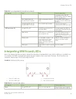
Page 162: ...ate with one WWN card but will be in degraded condition If you have removed a card be sure to replace as soon as possible NOTE Do not use steps in the WWN card and WWN card bezel removal procedures to...

Page 163: ...N card Error messages regarding WWN units in chassisshow output Error messages that may indicate problems with a WWN card are summarized in the following table TABLE 21 Messages that may indicate WWN...

Page 164: ...ow direction on WWN cards on page 171 4 Verify WWN card operation using steps under Verifying WWN card operation on page 172 Replacing WWN cards cold swap Use this procedure to replace WWN cards with...

Page 165: ...cation audit will be run to detect any mismatches or other problems A second WWN card is enabled and the WWN card audit will be run If an error is detected during the audit EM 1220 and EM 1222 message...

Page 166: ...2 System AirFlow Non portside Intake Header Version 2 Power Consume Factor 1W Factory Part Num 60 1003194 02 Factory Serial Num DZH0331L032 Manufacture Day 3 Month 10 Year 15 Update Day 0 Month 0 Year...

Page 167: ...e a Phillips screwdriver to tighten the captive screw and secure the card assembly to the chassis NOTE Be sure that captive screws are tightened If not high pressure from fan operation may unseat card...

Page 168: ...on the new cards using the ipaddrset command 1 Unpack the replacement WWN card assembly and save the packaging for the faulty WWN card s The WWN card assemblies are labeled 1 for the left slot and 2...

Page 169: ...perating problems 9 Determine the active CP blade by entering the haShow command 10 On the active CP blade run the wwnrecover command and specify WWN 2 card for recovery when prompted in wwnrecover ou...

Page 170: ...sis and set it aside The ends of both WWN card assemblies with pull tabs are now visible 2 Unscrew the captive screw for the WWN card assembly using a Phillips screwdriver until the assembly releases...

Page 171: ...figuring system airflow direction to Non portside Intake If airflow direction for power supply and fan assemblies does not match WWN cards will not automatically reconfigure and the fan or power suppl...

Page 172: ...e fan to both WWN cards Enter Selection 1 WWN Airflow direction recovery complete Please reboot the system 4 Reboot the system Verifying WWN card operation Perform the following tasks to verify operat...

Page 173: ...of the same type and match the airflow of installed fan assemblies Power supply model supporting nonport side air intake NPI provides 1450 W 100 120 VAC and 2870 W 200 240 VAC This assembly has two fa...

Page 174: ...converts AC or DC input to the required DC output power required for device operation Each HVAC HVDC power supply assembly provides the following power outputs in Watts at the indicated AC and DC inp...

Page 175: ...wer supplies can be removed and replaced without special tools If you are replacing one power supply in a configuration with N 1 or greater redundancy the director can continue operating during the re...

Page 176: ...number P N as the FRU being replaced to provide the same airflow The manufacturing P N located on the top of the FRU contains either NPI or NPE If a mismatched power source or fan assembly is installe...

Page 177: ...ort side This symbol should appear on FRUs with part numbers that contain an NPE Ensure airflow direction of power supply and fan assemblies match If power supply or fan air flow direction does not ma...

Page 178: ...ed If not high pressure from fans operation may unseat power supply assemblies from chassis connectors Refer to Safety precautions on page 21 for caution and danger notices related to installing power...

Page 179: ...to the new power supply assembly from power source 4 Verify power supply assembly status LED Replacing power supply assembly hot swap If your chassis is up and running but a power supply has failed co...

Page 180: ...se of power supply failure and other specifications If there is insufficient power the chassis will power down blades until the power demand can be met 2 Perform one of the following steps If you need...

Page 181: ...slot and tighten captive screw to secure to chassis Installing a power supply To install a power supply complete the following steps 1 If a filler panel is installed over the slot where you are insta...

Page 182: ...licy Suite MAPS monitoring follow procedures to update the active MAPS power supply switchstatus policy settings for four PSU devices in the Additional MAPS features section of the Brocade Monitoring...

Page 183: ...mand Reference for output examples and additional information on Fabric OS commands For more information about error messages refer to the Brocade Fabric OS Message Reference Verifying power supply op...

Page 184: ...Brocade X6 8 Director Hardware Installation Guide 184 53 1004105 07...

Page 185: ...eration Fan assemblies with the following airflow directions can be installed All fan assemblies must have the same airflow direction and match airflow direction of installed power supplies Fan assemb...

Page 186: ...ow You must order a replacement FRU with the same part number P N as the FRU being replaced to provide the same airflow The manufacturing P N located on the top of the FRU contains either NPI or NPE I...

Page 187: ...rt side This symbol should appear on FRUs with part numbers that contain an NPI The green E symbol indicates an exhaust FRU This unit pulls air in from the port side of the device and exhausts it out...

Page 188: ...re inside chassis may unseat these FRUs from chassis connectors Fan assembly numbering The following figure illustrates the location and number identification of fan assemblies in the chassis FIGURE 5...

Page 189: ...status of fan assembly displays absent or faulty check if assembly is seated in chassis If it is power supply could be faulty or is not receiving power for some reason Enter sensorShow to determine if...

Page 190: ...led fan assembly complete the following steps 1 Shut down the system using the sysShutdown command 2 Unplug power cords from receptacles on all power supply assemblies 3 Remove faulty fan assembly 4 I...

Page 191: ...heating and eventual system shutdown 3 Loosen the captive screw at each end of the fan assembly until the screw releases from the chassis Use a 1 Phillips screwdriver if tightened 4 Grasp the handle a...

Page 192: ...nd other diagnostic tests For information on interpreting LED patterns refer to Interpreting fan assembly LEDs on page 96 2 Check the fan assembly status using the following commands fanShow Displays...

Page 193: ...place If you run the chassis with an uncovered slot the system will overheat Blade filler panels have a latch mechanism at each end of the panel Both latches must be opened to remove and install the p...

Page 194: ...elease Installing a filler panel 1 Pull out the spring loaded latch release on the latch at each end of the cover using your thumb and forefinger and slide the latches toward the center of the cover 2...

Page 195: ...ends pushing the cover firmly into the slot then latching both ends again NOTE Be sure filler panels are securely latched If not high pressure from fan operation may unseat blade from chassis connect...

Page 196: ...Brocade X6 8 Director Hardware Installation Guide 196 53 1004105 07...

Page 197: ...ling the cable management comb Time and items required for removal and installation The replacement procedure for the cable management comb takes less than five minutes A 1 Phillips screwdriver is req...

Page 198: ...comb Complete the following steps to replace the cable management comb 1 Position and tighten the four 4 screws to secure the cable management comb to the chassis 2 Arrange the cables along the cable...

Page 199: ...ide of the door Each hole snaps into a ball stud located on a matching corner of the chassis Time and items required The first time installation procedure for the chassis door takes 15 minutes or long...

Page 200: ...cement of the chassis door Installing a chassis door Complete the following steps to install the door on the port side of the chassis Installing a chassis door Brocade X6 8 Director Hardware Installat...

Page 201: ...ng the bezel to the bracket using a Phillips screwdriver One screw is located above the bracket and one beneath the bracket at bezel center Do not remove the bezel mounting bracket 1 from the chassis...

Page 202: ...ide of the rear of door with the ball studs on each chassis mounting ear Push door onto chassis to snap onto the studs FIGURE 64 Removal and replacement of the chassis door Installing a chassis door B...

Page 203: ...peration and configuration NOTE New WWN cards are shipped preinstalled in the replacement chassis Do not replace the WWN cards in the replacement chassis with the old WWN cards from chassis that you a...

Page 204: ...ying correct operation of system on page 213 9 Verifying correct operation of system on page 213 Chassis fault indicators Verify that replacement of the chassis is necessary If error messages and LED...

Page 205: ...chassis 1 and 2 Phillips screwdriver Use 1 Phillips screwdriver for removing and installing blades and FRUs in chassis Preparing for replacement Before beginning replacement procedures you must run t...

Page 206: ...on information Location of config switch txt file Location of config miscinfo txt file IP address subnet mask WWN for the device SAN profile Location of SANbefor txt file Notes regarding nsshow output...

Page 207: ...40 0 Host Name cp0 Gateway IP Address 10 33 48 1 CP1 Ethernet IP Address 10 33 60 87 Ethernet Subnetmask 255 255 240 0 Host Name cp1 Gateway IP Address 10 33 48 1 Backplane IP address of CP0 10 0 0 5...

Page 208: ...eSzRScycazfT0G Trunking license RyeSzRScycS0fT09 4 Domain Fabric license 8 Enter supportShow then copy the command output into a text file named spptshow txt NOTE The supportShow command has a very lo...

Page 209: ...them aside Transceivers without integrated cables can be left in the blades or removed 6 Disconnect all cables from the CP blades Removing components from the chassis Follow electrostatic discharge ES...

Page 210: ...rcle the packaging b Open the top of the shipping box and remove accessory kit rack mount kits and foam from the top of the chassis c Lift the cardboard shipping container and inner cardboard sleeve o...

Page 211: ...on device Refer to Providing power to the device on page 48 The device performs a power on self test POST The POST takes a minimum of three minutes and is complete when LED activity returns to the st...

Page 212: ...e as admin switch admin login login admin password xxxxxxxx switch admin NOTE If you are using the Virtual Fabric feature you must run configdownload vf before running the configdownload command to re...

Page 213: ...password xxxxxxxx switch admin 2 Enter the chassisShow command to verify that airflow direction set on WWN cards matches airflow direction for fans in fan and power supply assemblies installed in devi...

Page 214: ...tion switch15 admin switchshow switchshow switchshow switchName sw15 switchType 166 0 switchState Online switchMode Native switchRole Subordinate switchDomain 1 switchId fffc01 switchWwn 10 00 00 23 f...

Page 215: ...file is recommended You must be logged in with Admin privileges 1 Create an after SAN profile by entering the following commands and copying the output to a text file named SANafter txt nsShow nsAllS...

Page 216: ...e new chassis Refer to the Brocade Fabric OS Administration Guide for information on SCC policy Use the wwn command to determine the WWN of the chassis Use the secPolicyAdd command to modify an existi...

Page 217: ...chassis 384 ports with 32 Gbps data rate plus 32 4x32 Gbps ICLs ISL trunking Can use up to 8 ports in a trunk group to form a 256 Gbps trunk UltraScale ICL bandwidth Brocade X6 4 Director 2 Tbps 16 U...

Page 218: ...rol Data traffic types Fabric switches supporting unicast multicast 255 groups and broadcast Media types FC32 48 port blade supports Brocade hot pluggable 32 Gbps SWL LWL SFP28 16 Gbps SWL LWL ELWL SF...

Page 219: ...sed on activity and status of all four lanes Bicolor green and amber Fibre Channel port status on extension blades displaying eight different LED states based on port activity and status Bicolor green...

Page 220: ...kg 54 lb 68 95 kg 152 0 lb Weight includes all blades and two power supplies Brocade X6 4 Director with Airflow Diverter and Port Side Exhaust Kit 40 00 cm 15 75 inches 43 74 cm 17 22 inches 61 29 cm...

Page 221: ...t Scale 1 12 Grms Air flow Brocade X6 8 Maximum 1711 cmh 1007 cfm Brocade X6 8 Nominal 985 cmh 580 cfm Brocade X6 4 Maximum 953 cmh 561 cfm Brocade X6 4 Nominal 486 cmh 286 cfm N A Heat dissipation Br...

Page 222: ...utput redundancy in case of single power supply failure Although examples for different port and blade configurations are provided for more information and help with determining the actual number of p...

Page 223: ...tem power but two must be installed to provide power efficiency and redundancy Brocade X6 4 fully loaded 2 CP blades 2 CR blades 4 FC32 48 port blades 2 fan assemblies Brocade X6 8 2647 W 9034 BTU hr...

Page 224: ...C high line 200 240 VAC One power supply provides system power but two must be installed to provide power efficiency and redundancy Brocade X6 4 fully loaded 2 CP blades 2 CR blades 4 FC32 48 port bla...

Page 225: ...00 VDC 2 power supplies for AC low line 100 120 VAC 1 power supply for AC high line 200 277 VAC One power supply provides system power but two must be installed to provide power efficiency and redunda...

Page 226: ...ades 2 CR blades 8 FC32 48 port blades 3 fan assemblies Power consumption modules For blades in the following table Idle blade enabled chips initialized no optics ports disabled Nominal blade enabled...

Page 227: ...2 300 m 984 ft OM3 550 m 1 804 ft OM4 N A N A 62 5 33 m 108 ft N A N A 9 N A 10 km 6 2 miles N A 16 50 35 m 115 ft OM2 100 m 328 ft OM3 125 m 410 ft OM4 N A N A 62 5 15 m 49 ft N A N A 9 N A 10 km 6 2...

Page 228: ...al Description 1 Not supported NA 2 Not supported NA 3 UART1_RXD Transmit data 4 GND Logic ground 5 GND Logic ground 6 UART1_TXD Receive data 7 Not supported NA 8 Not supported NA Serial port specific...

Page 229: ...aste electrical and electronic equipment EU WEEE 94 62 EC packaging and packaging waste EU 2006 66 EC batteries and accumulators and waste batteries and accumulators EU battery directive 1907 2006 of...

Page 230: ...Brocade X6 8 Director Hardware Installation Guide 230 53 1004105 07...

Page 231: ...003 Class A Cet appareil num rique de la classe A est conforme la norme NMB 003 du Canada CE statement ATTENTION This is a Class A product In a domestic environment this product might cause radio inte...

Page 232: ...ect the interference at the user s own expense KCC statement Republic of Korea Class A device Broadcasting Communication Device for Office Use This device obtained EMC registration for office use Clas...

Page 233: ...indique une d faillance ou une panne de courant v rifiez que le ventilateur est bien log dans le ch ssis et que les vis qui fixent le ventilateur au ch ssis sont bien serr es Si les vis sont desserr e...

Page 234: ...supplies and fan trays are clearly labeled with either a green arrow with an E or an orange arrow with an I VORSICHT Vergewissern Sie sich dass die Luftstromrichtung des Netzteils der eingebauten L f...

Page 235: ...N No intente levantar ni sostener el chasis sujetando el bisel del logotipo colocado sobre las ventilas que se encuentra al lado del puerto Ethernet de la puerta CAUTION Remove the logo bezel protect...

Page 236: ...ispositivo sea conforme a la certificaci n NEBS utilice un cable de conexi n a tierra de calibre AWG 2 como m nimo El cable de conexi n a tierra debe disponer de un conector engarzado homologado sumin...

Page 237: ...d l uft das System hei MISE EN GARDE Si vous n installez pas de module ou de bloc d alimentation dans un slot vous devez laisser le panneau du slot en place Si vous faites fonctionner le ch ssis avec...

Page 238: ...nen Un nonc de danger indique des conditions ou des situations potentiellement mortelles ou extr mement dangereuses Des tiquettes de s curit sont pos es directement sur le produit et vous avertissent...

Page 239: ...age hydraulique ou lectrique pour l installation PELIGRO Un chasis con la configuraci n incomplete pesa aproximadamente 35 61 kg 78 5 libras y requiere un elevador hidr ulico o asistido para realizar...

Page 240: ...ntie dass das Stromkabel sicher mit Ihrem Ger t verwendet werden kann DANGER Si l installation n cessite un cordon d alimentation autre que celui fourni avec le dispositif assurez vous d utiliser un c...

Page 241: ...es metteurs r cepteurs optiques certifi s par Brocade Communications Systems Inc et conformes aux exigences sur la puissance de rayonnement de cat gorie 1 de la FDA d finies au sous chapitre 21 CFR I...

Reviews: