15
IT
ENG
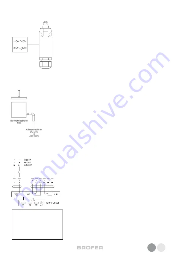
Magnetic command
Where necessary, an electromagnet can be installed on the damper so as to anticipate the clos-
ing of the damper before the thermo fuse is triggered. Depending on the type of electromagnet
(current input or breaker), it will send or cut off the electric power signal and the damper will
close to prevent the diffusion of cold fumes.
If a fire breaks out, when the temperature rises the thermo fuse will override the action of the
electromagnet.
Magnet technical specs
- Retaining force: 120N
- Protection rating (EN 60529 Standard): IP40
- Absorbed current at 20°C: 1.6W (none) - 3.5W (emission)
- Operating temperature: from -30 to +85
MOTORISED COMMAND FUNCTIONS, DATA AND ELECTRICAL WIRING LAYOUT
The motor is powered by connecting it to the mains (contacts 1 and 2) which
moves the damper shutter to the open position, whilst simultaneously loading
the spring which retains all the power needed to close the duct in case of and
alarm or black-out.
The connections of the two limit switches inside the motor can be used to ren-
der the rest of the system more flexible; for instance, by connecting contacts
S1 and S2, it will be possible to trigger the shutdown of the fan unit should
the damper shutter close, whilst contacts S4 and S6 can be used to trigger
an alarm pilot light.
The thermoelectric device consists of three fuses: these make the fire damper
shutters sensitive to the temperature inside the duct (with Tf 2 and Tf 3 fuses
which can be replaced) and to ambient temperatures (using the Tf 1 fuse).
When the device is triggered, it locks down the power supply irreversibly, until
the fuses are replaced, which allows the servomotor to move the shutter into
the closed position using the force of the spring.
It also has a button that can be pressed manually to simulate a triggered fuse
and allow testing and inspection of the shutter.
Its position outside the damper and self-threading screw fasteners allows for
safe control over ambient temperatures and easy maintenance.
• Allacciamento 24V:
da trasformatore
• Allacciamento 230V:
per l’interruzione della rete prevedere
un dispositivo di sezionamento di
tutte le fasi (apertura dei contatti
min. 3mm)
MANUAL COMMAND FUNCTIONS, DATA AND ELECTRICAL WIRING LAYOUT
Start and end stroke microswitches
The devices that signal the start stroke and end stroke are two independent NC+NO
dual contact switches.
The first normally closed (NC) on contacts 21 and 22, whilst the second normally
open (NO) on contacts 13 and 14.
When the switch is triggered, the contact status is inverted, the NC contact opens
and the NO contact closes.
E.g.: the relay that controls the fan power supply is connected to contacts 21 and 22
(NC), whilst a luminous alarm indicator is connected to contacts 13 and 14 (NO). In
this case, when the damper shuts, the fan will switch off and the alarm indicator
pilot light will come on.
Switch technical data
-Casing: Fibre glass reinforced thermoplastic
-Protection rating (EN 60526 Standard): IP65
-Cable cross-section diameter: rigid 2.5mm² - flexible with ferrule 1.5 mm²
Operating temperature: from -25 to +70


