10
10. MANUAL COMMAND FUNCTIONS, DATA AND ELECTRICAL WIRING LAYOUT
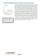
Start and end stroke microswitches
The devices that signal the start stroke and end stroke are two independent NC+NO
dual contact switches. The first normally closed (NC) on contacts 21 and 22, whilst
the second normally open (NO) on contacts 13 and 14. When the switch is triggered,
the contact status is inverted, the NC contact opens and the NO contact closes. E.g.:
the relay that controls the fan power supply is connected to contacts 21 and 22 (NC),
whilst a luminous alarm indicator is connected to contacts 13 and 14 (NO). In this
case, when the damper shuts, the fan will switch off and the alarm indicator pilot
light will come on.
Switch technical data
- Casing: Fibre glass reinforced thermoplastic
- Protection rating (EN 60526 Standard): IP65
- Cable cross-section diameter: rigid 2.5mm² - flexible with ferrule 1.5 mm²
Operating temperature: from -25 to +70
Magnetic command
Where necessary, an electromagnet can be installed on the damper so as
to anticipate the closing of the damper before the thermo fuse is triggered.
Depending on the type of electromagnet (current input or breaker), it will send
or cut off the electric power signal and the damper will close to prevent the
diffusion of cold fumes. If a fire breaks out, when the temperature rises the
thermo fuse will override the action of the electromagnet.
Magnet technical specs
- Retaining force: 120N
- Protection rating (EN 60529 Standard): IP40
- Absorbed current at 20°C: 1.6W (none) - 3.5W (emission)
- Operating temperature: from -30℃ to +85℃
Electromagnet
MD
Power supply
DC 24 V or CA 20 V


