11
11. MOTORISED COMMAND FUNCTIONS, DATA AND ELECTRICAL WIRING LAYOUT
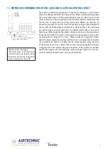
The motor is powered by connecting it to the mains (contacts 1 and 2) which
moves the damper shutter to the open position, whilst simultaneously loading
the spring which retains all the power needed to close the duct in case of and
alarm or black-out. The connections of the two limit switches inside the motor
can be used to render the rest of the system more flexible; for instance, by
connecting contacts S1 and S2, it will be possible to trigger the shutdown of
the fan unit should the damper shutter close, whilst contacts S4 and S6 can
be used to trigger an alarm pilot light. The thermoelectric device consists of
three fuses: these make the fire damper shutters sensitive to the temperature
inside the duct (with Tf 2 and Tf 3 fuses which can be replaced) and to ambi-
ent temperatures (using the Tf 1 fuse). When the device is triggered, it locks
down the power supply irreversibly, until the fuses are replaced, which allows
the servomotor to move the shutter into the closed position using the force
of the spring. It also has a button that can be pressed manually to simulate
a triggered fuse and allow testing and inspection of the shutter. Its position
outside the damper and self-threading screw fasteners allows for safe con-
trol over ambient temperatures and easy maintenance.
- 24V Connection: transformer
- 230V Connection: for the interruption
of the network must incorporate a device
which disconnects the phase conductors
(contacts opening min. 3mm) ℃
Thernal fuse


