5
5. INSTALLATION IN BRICK WALLS
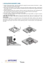
1 Before commencing installation, check the condition of the damper, the correct position of the shutter, in a closed
position, and that the command works properly.
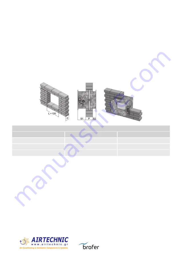
2 Make a hole in the wall which is 120 mm large in H and L than the nominal damper measurements (fig.1).
3 Position the damper inside the hole centring it horizontally, making sure the shutter axis corresponds to the wall
axis. Maintain the axis of rotation of the blade horizontal as from tests carried out (is not allowed to be installed
with vertical axis). Respect the dimensions shown (fig.2 - table 1).
4 Fill in the space between the wall and the damper using fireproof cement material (M10 cat. or higher) to reinstate
resistance and insulation (fig.3).
On completing installation, it is recommended to run a test to check the blade rotates correctly and the commands
work properly (in both manual and motorised mode). It can be conducted in manual mode by using the lever to reset
the damper and pressing the test button to simulate operating functions. In motorised mode, use the thermoelectric
fuse lever.In motorised mode, use the thermoelectric fuse lever.
fig. 1
fig. 2
fig. 3
TABLE 1
P (mm)
S1 (mm)
S2 (mm)
120
190
90
150
175
75
> 150
175
= 400 - (P+S1)


