6
6. INSTALLATION IN CONCRETE FLOORS
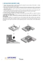
1 Before commencing installation, check the condition of the damper, the correct position of the shutter, in a closed
position, and that the command works properly.
2 Make a hole in the wall which is 150 mm large in H and L than the nominal damper measurements, and position the
metal brackets accessories (only when positioning it with the command side above the floor) aligning them with the
edge of the hole (fig. 1).
3 Insert the damper inside the hole, positioning it with the command side above the floor so that it protrudes by 175
mm. Push the brackets against the damper casing so that it is blocked in the correct position (fig.2).
5 The metal brackets are designed to be fastened to the floor (fig.3).
6 Fill in the space between the floor and the damper using fireproof cement material (M10 cat. or higher) to reinstate
resistance and insulation (fig.4).
PLEASE NOTE: if the damper is fitted with the command side below the floor, make sure it protrudes by 175 mm
below the latter.
On completing installation, it is recommended to run a test to check the blade rotates correctly and the commands
work properly (in both manual and motorised mode). It can be conducted in manual mode by using the lever to reset
the damper and pressing the test button to simulate operating functions. In motorised mode, use the thermoelectric
fuse lever.
fig. 1
fig. 3
fig. 2
fig. 4


